Buying the Unit
For me to buy a broken unit from overseas means the unit is pretty cheap. In this case it was cheap but not super cheap. I asked the seller what options were included and he said it included the ovenised time-base. I figured just the parts value was high enough to be work it. He also said the unit hadn't been opened.
I placed the order and waited for the ebay shipping program to get it here. The shipping cost wasn't too bad.
When it arrived the first thing was the box was atrocious -I am amazed it made it here at all. The cardboard was soft and while in contained packing peanuts there was nothing to stop it moving around. Total rubbish!
The next problem was that when I picked up the unit it rattled. The screws were loose and it clearly had been opened before. The power supply board wasn't even screwed in and was rattling loose inside the box
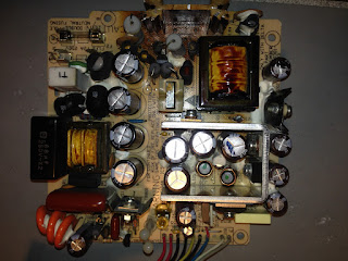
So I started looking at the power supply and not only had it been removed but a repair had been attempted. What I found was that
- The main switching transistor (on the big heatsink) was missing.
- A Zener diode (ZD1) near the switcher was missing
- A diode was missing
- The main filter caps had been replaced (and with 250V rated ones although this turned out to be ok - see below).
- The fan was missing
I approached the seller about this. I didn't really want to send it back as then I lose the shipping twice. We negotiated a reduced sale price and I notched this up to experience.
He is still selling stuff though and he has another advert with the same misleading text and similar blurry photo. The seller is mannd1deborah Here is one of his dodgy ads. You've been warned!
He is still selling stuff though and he has another advert with the same misleading text and similar blurry photo. The seller is mannd1deborah Here is one of his dodgy ads. You've been warned!
The Damage
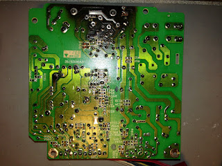
The power supply seems to have suffered a pretty catastrophic failure of the main switching transistor. There is a significant scorch mark on the PCB around it and a few associated components have been removed by whoever attempted the repair.
A few of the tracks lifted in the area around where it got hot. Also on the secondary side there is a diode with some adjacent heat damage to the board. The fact that the fan was missing made me think it must have failed and caused the power supply to overheat.
Missing Parts
I downloaded the component level service manual from Keysight for the unit but unfortunately it doesn't include the schematics of the power supply. The power supply is labeled 'SMP-43DP' in the silkscreen and 'SMP-43DL' on the bottom of the metal plate that holds it and is made by Delta.
I tried contacting Delta but they said they had no records on it and told me to contact Keysight. I contacted Keysight and got nothing. In fact you can buy the power supply as a spare part but when I asked about it my email was never responded to.
In the past when I repaired a switch mode supply like this the first thing would be to look up the datasheet for the main switching controller IC as often the circuit is very similar to the typical one listed in the datasheet. In this case however the unit is old enough that it doesn't have an IC controlling it.
My first assumption was that the main transistor would be some kind of switching MOSFET. I asked on the HP/Agilent Test equipment yahoo group and someone pointed out that the zener diode going to one of the transistor legs is connected to the positive rail of the main filter caps (i.e. 340V) so that wouldn't be much good for clamping a gate. The conclusion was that it must be a bipolar transistor.
Also the guy on the yahoo group explained why the capacitors are only rated for 250V - the thing is there are four of them and they are not all in parallel but the arrangement is more complicated. It turns out the supply contains a circuit for detecting the mains input voltage and if the voltage is around 100-110V it will use the bridge rectifier in a configuration where it doubles the voltage (there is a good description of how this works here). The upshot is that if the supply is running somewhere like the US where the mains voltage is 110V then the point between the pairs of capacitors is .at the input voltage but in Europe or Australia then the caps in series have 220/240V across them (in total).
There are a bunch of youtube videos where people teardown or repair these counters (such as this one and this one). The problem is that all of these have a different version of the supply. So even if I could see the parts in question then they will be different. Someone called JF2014 even posted a schematic on the EEVBlog of a 53131A supply but it too was for the other version).
Subterfuge and Guile
So then what are the missing parts? So I started looking at transistors rated for 1000V VCE and ones that could handle a couple of amps. What worried me is that guessing might result in a charred mess.
I found a guy selling a replacement power supply for a 53131A on Amazon and US ebay (doesn't ship internationally) which was the same version as mine. He wanted more for the supply than I paid for my unit (and shipping) so it wasn't an option.
I contacted him and asked very nicely if he would read the numbers off the big transistor and the adjacent zener diode. After a couple of emails back and forward (including some pictures and arrows) he said the transistor was a BUV48A. Winner! I didn't have the heart to ask him to go back and get the numbers off the zener however.
So luckily this transistor is available on RS - not cheap but available. So good news as now I have the most critical part covered.
So luckily this transistor is available on RS - not cheap but available. So good news as now I have the most critical part covered.
Other Parts
After much googling I figured out the fan is a Fonsan Delta DFB0412M. Believe it or not I found some parliamentary expenditure report that listed 53131A and the fan part number. Since then I found a fair bit of discussion about using quieter fans and Gerry Sweeney modified his counter to switch off the power when the switch is clicked. Anyway I found a seller on ebay that sells the original fan and ordered one (again - not cheap).
So the missing diode was likely to be exactly the same as the one next to it which was a RFP203 - a chunky 4A, fast recovery diode intended for swithmode supplies. I found a suitable (i.e. fast and high current handling capability) replacement and ordered one. The diode on the secondary side was much smaller and was in a tight spot so using the chunky diode wouldn't work. I ended up just ordering a EGP20D.
Zener Diode
So now I only had one part to work out and that was the zener diode. The only thing I could think of was to draw out the circuit and try to work out what voltage rating it needed to have.
Initially I started drawing the entire circuit but this was pretty time consuming and it occurred to me that I only needed to work out the part near the switching transistor.
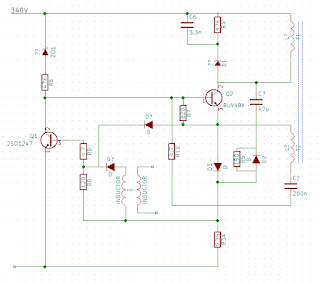
I sketched out the following:
While probing around to draw the circuit I noticed a short in places where I didn't expect to see one. It looked like the short was Q1 so I removed it from the board and sure enough it was dead. Unfortunately it is a discontinued Sanyo part (2SD1247) so I ordered some NOS from Greece on ebay.
There are a few interesting things here:
- The frequency is determined by the resonant frequency of the transformer primary and other capacitors
- The feedback is provided not by an opto-coupler but by a transformer! Talk about old-school.
The problem was I couldn't see what would need the voltage drop of ZD1. It looked too me like if you removed ZD1 the 47K resistor (R6) would limit the current enough that it would all work. I put the circuit into LTSpice and by measuring a few inductances and capacitances using my LCR meter I could get the circuit to run under simulation (even with the wrong transistor models). The problem is it didn't seem to make a big difference if I made the zener 10V or 200V.
I put up a question on EEVBlog but after a couple of days nobody replied. I then put up the same question on the HP forum and I got an answer - basically the zener prevents the supply from starting if the voltage on the capacitors is too low. So if instead of 110 the input voltage was 80V or if it was 180V instead of 220V this would prevent it running. Basically the zener needs to be rated for around 180V to prevent the circuit starting.
Putting it all Together
So the 180V zeners arrived from RS, the transistors from Greece and the fan was here. I had everything I needed and put it together.
I attached the supply to my isolation transformer, stood back and switched it on - I was elated to see the fan spin as this must mean the primary is switching! I did some more testing and found the 12V wanders a bit if the 5V is under no load (I used my dummy load to load up 5V as it is the highest current output). Otherwise all the output voltages were very good.
Crossing fingers and toes I connected it up to the counter and it worked!
I haven't checked the performance specification but it seems very close. The output of my signal generator measures to within 1Hz up to 20Mhz. They can't both be out by the same amount!
The annoying thing is the fan run constantly even when the device is off. The screen is just a little dim but quite usable. Overall this turned out to be a good score and another valuable learning exercise.


No comments:
Post a Comment