New Boards
The new boards look very sexy. They make much better use of space and the layout is more logical. While it still isn't easy to tighten the screws, it is much easier than the previous proto-type. Here it is nearly completed below.

With bated breath I tested it for the first time. I had massive expectations of the new high-precision shunt resistors and... It didn't work. After some head scratching I realized the expensive shunt resistor was 0.1 ohms instead of 0.01 ohms. I changed the amplifier to suit and this work but I also realized that the current limit for this resistor would be around 2A. I gave in, ordered the right resistor and then waited for it to arrive (don't ask how much).
When the right resistor arrived, I fitted it and tested the unit again. I was quite impressed with the current accuracy and overall everything was working well.
Load Testing and Overshoot
While waiting for the replacement shunt-resistor I was experimenting with the simulation and found that I could increase the capacitor in the voltage control circuit to reduce the overshoot. By increasing C20 to 20nF I could completely eliminate the overshoot and not effect the transient performance. I tested this and it did indeed behave this way.

One of the key changes in this version was that I moved the bridge onto the heat sink. I wanted to run some load tests to ensure this was successful.
My dummy load is only capable of 4A, I tried a slightly different approach which was to use a 1 ohm concrete resistor immersed in big cup of water. This worked really well as it takes quite a while for the water to heat up.
I found that with the current limit set over 4.5A that the output would oscillate. I thought it could be the supply is running out of headroom voltage on the capacitor but that wasn't it. I figured out that the additional capacitance I added to control the overshoot was causing the oscillation.
I figured out that if I increase the compensation capacitance on the current control amplifier I could get rid of the oscillation and still have a higher capacitance in C20 to reduce the over-shoot.
This still needs some thought but overall this is looking pretty good. One negative effect of increasing C20 is then the output voltage slew rate is much lower. It can take much longer for the output to hit the set point or for the voltage to recover after an overcurrent limit event. I still need to finesse this a bit but for now I am moving looking at other things.
Other Testing
I also finally got the courage to short the outputs and to verify the current limit behaves correctly and it did. The supply also behaves correctly with the current set to small values (like 10mA) now with the correction to the pre-regulator.
I tested the behaviour of the pre-regulator with a pulsed load. This would still not always recover back to the set voltage - particular in the 15-30 volt range. I ended up increasing the resistor in the peak-detector circuit (R52) to 100K and this worked. The only thing is that now in 30V mode it can get very hot with a pulsed load that drives the output down to low voltages (in the over-current events). In most circumstances this won't happen as either the over-current will lead to a constant state and the pre-regulator will adjust or the over current pulses will be infrequent.

Mains Input
Because the Raspberry Pi must be shutdown and can't just be turned off, I need to control the power to the Raspberry Pi and the main transformers separately. The ideas is there will be a permanent 5V supply but the main transformers will only be turned on when the Raspberry Pi is up.
I also need to deal with the inrush that occurs when the unit is powered up as three torroidal transformers feeding an array of capacitors will suck a considerable startup current.
I really need to keep this circuit stupidly simple, I don't have an isolation transformer or a differential probe and I don't want to have to debug it if I can get away with it. Also I can't proto-type this circuit on bread-boards or matrix board as - well that would be dangerous.
I came up with the idea of using two Solid State Relays (SSRs) and a power resistor to turn on the main supply and control in-rush. One SSR turns on the 240V supply via a power resistor and the second SSR shorts-out the power resistor. Both are activated by the Raspberry Pi when the software starts.
I use simple NPN transistor to switch on the relays using the 5V supply. The Pi generates 3.3V signals which activate the transistors. I designed the circuit to have an input and three output connectors so most of the mains wiring is routed through the PCB. Here is the circuit (below)

Main Input PCB
I didn't want to wait three weeks for this PCB to come back and it is quite simple to implement as a single sided board. I thought I would try my hand at etching the PCB at home.
I bought a small ($3) 80x50mm box from Jaycar that would hold the circuit. I'd have to either not use the lid or cut a lot of holes in it but I thought it would be better to put the mains circuit in a box. For starters it makes it harder to accidentally touch the live circuit and the box insulates the metal case from the PCB.
I designed the PCB to fit comfortably in the box. It looks like this:

The main things were to keep the power tracks fat and to place the low-voltage circuit as far away as possible from the main circuits. It was harder than I thought to get it to all fit in the box but I got it to work in the end.
Etching PCBs at Home
My plan was to use the toner-transfer method to etch the PCB. I don't have a laser printer at home so I used the local Officeworks store.
I printed the bottom side artwork as a PDF and asked KiCAD to include dots for the drill locations. Initially I flipped this but then realized that was wrong. The toner transfer process ends up flipping the artwork so this cancels the flip caused by the bottom side being printed when viewed from the top.
I copied and pasted the PCB so there would be four artworks per page and asked Officeworks to print me a few copies onto shiny (photo paper). I only really used one page but they were 35c each and I felt sorry for the lady as she had to fight the machine to put photo paper into the black and white laser copier.
I cut out the board artwork from the paper, cut out a piece of PCB the correct side and used sticky tape to keep the artwork aligned with the board. I used a laminator to heat the paper so the ink would transfer but I found even running it through the laminator a few times was not enough to transfer the ink reliably onto the paper.
I tried using a clothes iron and while this transferred the ink quite well it also melted the tape I used to hold it on (but that doesn't matter I think). The problem was that when I peeled the paper off it tended to take the print with it.
I did this a couple of times with no success. I had an idea that if I softened the paper with water it might leave the ink behind. This worked really well. I soaked the paper and gently wiped it off the board while leaving the ink behind.
I etched the board in Aluminium persulfate and the results were excellent! The image below shows the board as it came out of the etchant.

Drilling the holes was not much fun. I bought a set of fine drill bits that have larger shanks so you can hold them in a normal chuck. I used to drill press to do the drilling and mostly the holes lined up. The bigger holes for the power connectors wandered for some reason and some ended up a bit crooked. No matter overall.
Here is the board assembled

And here is the solder side.

Raspberry PI GPIO and Python
Controlling GPIO pins from Python is relatively straight forward. Initially I stupidly followed some guide that told you to install an ancient GPIO RPM which required the python program to run as root. Once I figured out the newer versions don't require this life got better.
You basically have to add an import and then setup the GPIO pins. You have to choose the naming scheme for the pins you are using between board and the naming scheme of the Broadcom chipset (as the pin names change between versions of the PI). Then you can set or read the pins. In addition I found a 'cleanup' method that resets the pins back to what they were when you started. I added a 'finally' exception handler to do this when the program exits so the mains is not left turned on.
Here is a summary of the code (some bits omitted).
import RPi.GPIO as GPIO
...
def setupIOs(): print "Setting GPIO 23 and 24 to outputs" GPIO.setmode(GPIO.BCM) GPIO.setup(23, GPIO.OUT) GPIO.setup(24, GPIO.OUT) def turnOnSupply(): print "Enabling 23" GPIO.output(23,True); time.sleep(1) print "Enabling 24" GPIO.output(24,True); time.sleep(1) pass def turnOffSupply(): print "Enabling 23" GPIO.output(23,False); GPIO.output(24,False); if __name__ == '__main__': try: setupIOs() turnOnSupply() LabPowerSupplyCtrlApp().run() finally: turnOffSupply() GPIO.cleanup()Case
At this point it is time to start figuring out how this thing will look when it is finished. With the new wide but shallow boards I figured out I can make it all fit with a depth of around 300mm and a width of around 420mm. The Raspberry Pi touch screen needs about 130mm.
I found that one of these 3U rackmount cases from Jaycar would pretty much do the job.
The case is built from these rails that look like meccano pieces as they have holes all the way along. The top, bottom, front and back can be unscrewed and the case is held together by the sides and rails.
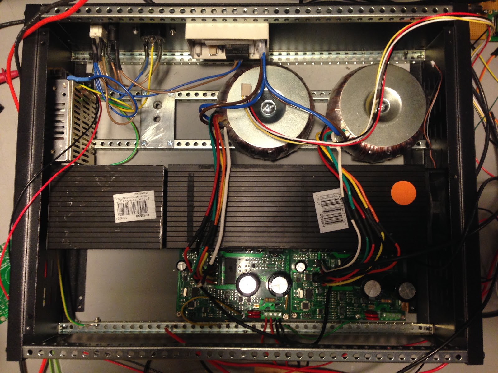
They provide four extra rails so I decided to use these to support the transformers and the heatsinks. I made small steel plates that screw to the rails and that have a hole for a bolt to support the transformer. I have round metal plates and rubber protectors that I can use to bolt the transformers down. The plates were made from some bracket I bought from the hardware store (Bunnings). This is what they look like in the case (excuse the messy wiring in the way).

I cut holds for the IEC connector, power switch and fuse into the back plate. I drilled holes through the back plate for the small box that holds the power input PCB and mounted that. The PCB just clips into the enclosure.

The I drilled and tapped the heatsinks for the components from the power supply. I figured out that if I measure, drill and tap the holes then screw the components on and then solder them to the board I can get them to line up perfectly. I drilled and tapped holes in the bottom so they could be screwed into the rails and the rails screwed into the case. I fitted a 12V fan onto the end of the heatsink channel and there are enough holes in the case sides that this will work.
I only had two of the long heatsink channels so I bought a third. I cut this channel in half using a drop saw. The cutting worked surprisingly well although did fling aluminium all over my shed. So now I have the big heatsink with two channels and a smaller one for the third channel.
I needed a 5V supply that can deliver 2A to feed the Raspberry PI. I found a Traco supply on ebay at a reasonable price and mounted that to the side wall. Here is the supply:

The 5V supply is tucked behind the heat-sink on the left of the case.

Here is the overall layout of the box at the moment.
Only two channels have been assembled right now and I have two transformers setup. I had to extend the transformer wiring to make it over the heatsink to the PSU boards but that went Ok.
The protective ground is a problem as the black powder-coated plates are pretty non-conductive. Currently it is organised as follows:
- The ground comes in and ties to the transformer rails where splits to ground the 5V supply and another ground wire goes forward to the front rail.
- Each of the power supply channels connects to the front rail ground
- There will be a ground binding post on the front panel connected to the front rail.
At some point I might scratch off some powder coating to ensure the sides and front/back are electrically connected to ground also.
Currently I have cut the hole for the Raspberry PI in the front panel but I think the only practical way to mount it is double-sided tape. The centre part of the display including the rapberry PI itself fits through the hole and the thin edge of the glass display will mount to the front panel with foam double sided tape.
I don't want to do this until the front panel is completely ready as otherwise I can't drill or work with it. I still need to drill holes for the outputs and for the soft-power switch and indicator LED.
Next Steps
I currently have the Raspberry PI running outside of the case with leads going back in for the USB connections to the channels, the 5V supply and the control signals for the power input.
I need to design the soft switch circuit that allows the PI to switch itself off when it is ready and the fan control circuit. I also want to build temperature sensing for each of the channels so the PI can control the fan.
We are getting close though! It is starting to look like something you might have in a Lab!