 In March 2015 I started designing a precision, low noise lab power supply. Sure I could buy one but where is the fun in that! I learned a lot about voltage regulation, and power circuits as well as ADCs, DACs and designing with precision in mind.
This page provides an outline of the project and links to the various blog posts that I wrote as I was developing the power supply.
So In general what I'd like is to have two or three output channels and the ability to run two in dual tracking mode. I'd like it to be at least as good as the Jaycar PSU I had before but more accurate, more programmable and to have a better UI.
The specs I ended up with were:
Specs
What I really wanted was one of those Rigol DP832A. Of course I could buy one but given I an am using this supply to learn about electronics it seemed a perfect opportunity to build one! Not to mention that the DP832A is close to $1000 here in Australia - that gives me a fair budget for the build!So In general what I'd like is to have two or three output channels and the ability to run two in dual tracking mode. I'd like it to be at least as good as the Jaycar PSU I had before but more accurate, more programmable and to have a better UI.
The specs I ended up with were:
- Three isolated output channels. 0-30V. 4.8A below 15V and 3A at 15-30V.
- Current limiting.
- Digitally settable output voltage.
- Displayed current, measured output voltage and power output.
- Ability to individually turn each channel on or off.
- High precision - 1mV/1mA resolution/
- Fast response to load transients (recovers in less than 20us) and minimal overshoots (around 100mV at max current output)
- Very low noise - less than 1mV RMS
- Reverse polarity protection (say if you connect a battery) fuses (both mains and DC).
- Safe grounded chassis,
- Ground terminal on front panel
I wanted the supply to be ultra quiet so not switching converters and a linear voltage regulator is required.
What I planned as extensions were:
- To be able to graph the current/power output like the Keysight bench meters do. Even show cumulative amount of energy consumed by the driven circuit. This means a decent graphical display is required
- To have an Ethernet interface. Maybe a web interface or for it to be LXI compatible or both.
- Some programmability (LXI). Doesn't have to be quick.
- Be able to save/load output configuration settings.
Most of this is not complete but the architecture of the implementation means I can support all of this in the future.
The project intro blog talks more about what I was originally thinking.
Architecture
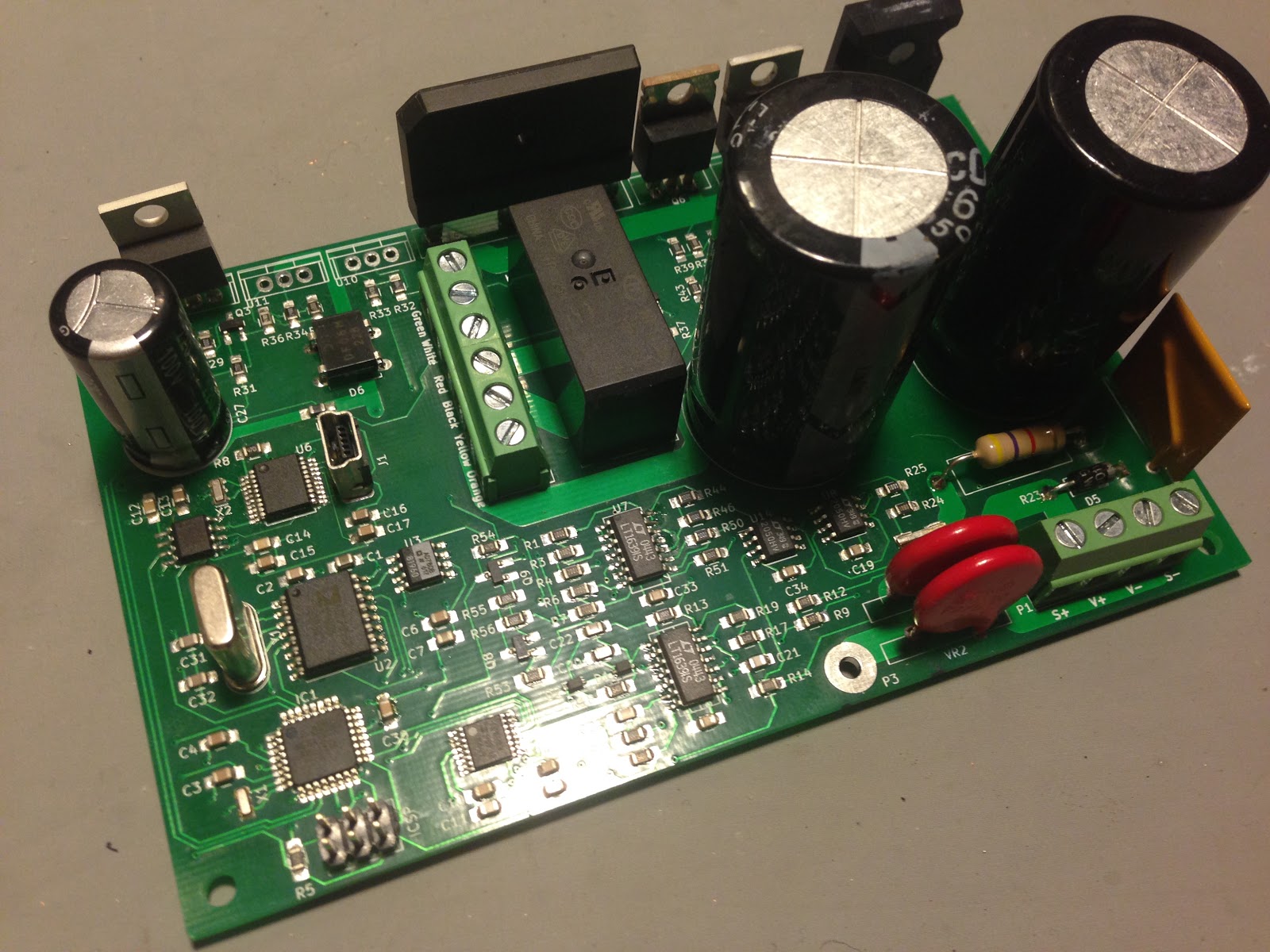
- Rather than one big board it makes sense for each supply channel to be separate. Bigger boards cost more and will take more debugging time.
- Big (high VA) transformers are expensive and to accommodate multiple channels the transformer would have to have lots of taps. More than likely this would mean a custom transformer so instead I plan to use three off-the-shelf torroidal transformers.
- A Raspberry PI based control interface.
- Each channels communicates with the control interface via isolated USB (each channel has an on-board micro-controller and isolated USB interface).
- Rather than muck around with designing a custom front panel I decided just to use a nice big high-res touch screen.
Also as this thing is a one-off I decided that using expensive components was a total non-issue. What's $10 for a chip in a supply designed to be the equivalent of a $1K commercial unit.
Heat Management
As this is a linear supply managing waste heat is a big factor. Managing the heat achieved by:
- Using a low-frequency (low noise) pre-regulator circuit that cuts charging to the bulk capacitors. More on the pre-regulator below.
- Large heat-sinks
- Temperature controlled fan
- Use of MOSFETs as the pass element and pre-regulator switching element to reduce the dropout voltage of the regulator.
In addition the circuit switches transformer taps for different voltage ranges. This doesn't provide much over the pre-regulator but does allow higher current output at lower voltages (4.8A vs 3A above 15V).
Pre-Regulator
Initially I experimented with using a circuit to switch on the power later in the cycle using an SCR based on the Jim Williams circuit detailed in Linear Technology AN32. See here for the first attempt.
The problem with this circuit is it generates considerable noise as it switches at the point where the current is maximal.
I found an alternative circuit on the EEVBlog forum that was reproduced by a member called BlackDog (from a design that came from elsewhere). In this design P-channel MOSFETs are used to switch off the current when the capacitor voltage reaches a target voltage. At this point the capacitor current is greatly reduced as the capacitors have charged.
In my version of this circuit I changed the voltage control to be a set level above the desired output and added circuitry to ensure the voltage didn't get thrown around too much if the supply goes into current limit mode.
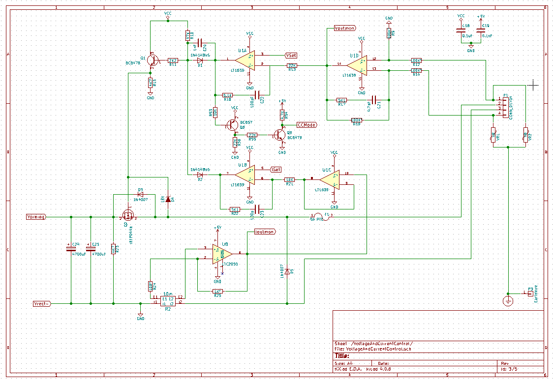
Voltage Regulator
The voltage regulation is built around an IRFP044N MOSFET. These proved to be pretty robust, had good thermal transfer and low enough gate charge to drive quickly for my purposes.
The problem is I need a gate voltage well above the output to make this work. Initially I used a voltage doubler circuit but this messed with the voltage waveforms under low-power enough that my pre-regulator wouldn't work.
In the end I decided to manually wind an additional winding onto the transformers and run this is series with the output winding. This gave the additional voltage I needed without much hassle.
I used LT1639 Op Amps to drive this as these could handle up to 44V supply voltage. In addition to the voltage control loop the circuit has differential voltage measurement from the output terminals to minimise the voltage differences due to internal resistances of tracks etc.
Current Sense
The supply uses low-side current sensing via a small resistor and a LTC2050HV op amp. The LTC part has spectacularly low offset voltage and precision but is relatively slow. This is fine for current limiting however.
I was initially using Welwyn wire power resistors but had lots of problems with the readings wandering as the resistor heated up. I eventually figured out this was a thermo-electric affect. I switched to precision vishay 4 terminal sense resistors which allowed me to reach the 1mA precision I wanted.
Digital Control and Reference
Each channel has an AD5689 DAC that sets the output voltage and current limit. I found some cheap AD780 references on ebay that are more than adequate for setting the DAC reference.
On the flip side the output voltage and current are read back by an AD7705 ADC.
Each channel has its own ATMEGA328P for controlling the DACs, switching transformer tap relays and reading back if the supply is in current limit. The microcontroller also handles linearization of the ADC/DAC using calibration tables stored in EEPROM,
The microcontroller communicates with the main system controller via an MCP2200 USB to serial converter. The serial signals are isolated from the rest of the channel using an ADUM1201 and the MCP2200 is powered from the serial bus.
Powering the Raspberry Pi
The Raspberry Pi cannot be powered off but must be allowed to shutdown gracefully. As a result the Raspberry Pi has its own switching supply that powers it and the touch screen.
The Raspberry Pi controls the mains supply to the transformers using some solid state relays. In addition this circuit switches in a resistor temporarily to reduce the in-rush created by the transformers and then a second SSR short circuits the limiting resistor.
There is a bi-colour LED that indicates the power state of the whole system and a momentary switch the user uses to turn on or off the entire system. A power control circuit based on a p channel MOSFET powers up the Raspberry PI when the button is pressed. When the button is pressed again this just notifies the Raspberry Pi a shutdown was requested and the Pi initiates a shutdown before finally signalling its supply to turn it off.
The Raspberry Pi also measures the temperature of each channel via a set of DS18B20 temperature sensors chained together on a 1-wire BUS. A 5 to 12V switching converter provides power for a small fan and the raspberry PI uses PWM to control the speed of the fan in response to the temperature of the system.
Raspberry Pi GUI
The user interface is built using the Kivy Pi Python toolkit. Python code polls the state of each channel and updates the GUI. Kivy Pi renders all of the buttons, text and other GUI widgets and handles touch events.
At the moment the GUI is pretty minimal and allows
- Each channel to be enabled/disabled,
- Displays the set voltage and current limit
- Displays the measured output voltage/current and power
- Displays the measured temperature
- Provides a tool to calibrate each channel using an LXI multimeter and to set the calibration table in EEPROM on each channel.
There is lots more that could be done here.
The Good the Bad and the Ugly
So what I liked about the supply is:
- It's pretty reliable and powerful
- Very precise
- Low noise
- Relatively quick to respond to load transients.
- The GUI is simple but quite nice and I think could be made very nice with a bit of work.
What I don't like
- The GUI is really slow. It's not the GUI itself but the fact that the system is polling three channels over relatively slow serial links. This makes the time between making a change and the change occurring relatively long.
- There is a small overshoot when the voltage is set or when it comes out of current limit. I reduced this a lot but I didn't want to compromise the speed. It's small enough not to be a concert (mVs)
- The banana sockets have enough resistance that the measurement of the voltage at the back of the terminals creates a few mV of error at the front of the terminals. I tried using 4 wire outputs but had stability issues. I may re-visit this.
What could have been done better:
- If I was designing it from scratch I would have made the additional transformer winding into two series windings and configured them to float above/below the output voltage. Then the entire control system would have been floating above the positive output rail and I could have used lower voltage (cheaper) parts.
Source Code and Schematics
All the source code and schematics are on Github and may be used for any purpose. If you decide to do something with my design consider buying me a beer!
The code was written in Atmel Studio. The PCBs were designed in KiCAD.
List of Major Components
- IRFP044N N-channel MOSFET as the pass device. http://www.irf.com/product-info/datasheets/data/irfp044n.pdf
- IRF5210 P-channel MOSFET used to switch the input in the pre-regulator http://www.irf.com/product-info/datasheets/data/irf5210.pdf
- MCR-100 SCR http://www.onsemi.com/pub_link/Collateral/MCR100-D.PDF
- LT1639 Op Amps used in the control loop. http://www.linear.com/product/LT1639
- LT1716 Comparator used in the pre-regulator http://cds.linear.com/docs/en/datasheet/1716fa.pdf
- LTC2050 Op Amp used for current sense amplifier. http://www.linear.com/product/LTC2050
- AD5689R DAC with built in 2ppm/degree reference as main output voltage/current DAC. http://www.analog.com/media/en/technical-documentation/data-sheets/AD5689_5687.pdf
- AD7705 ADC used to read output voltage/current http://www.analog.com/media/en/technical-documentation/data-sheets/AD7705_7706.pdf
- ATMEGA328P Used as the main controller
- ADUM1201 dual channel isolator used to isolate the USB interface from the rest of the module http://www.analog.com/media/en/technical-documentation/data-sheets/ADuM1200_1201.pdf
- MCP2200 USB to serial converter http://www.microchip.com/wwwproducts/devices.aspx?dDocName=en546923
 List of Blog Articles

Voltage Regulator Test
Pre-regulator
Pre-regulator
Progress!
Current sensing/limiting
Current Sensing/Limiting (Testing)
Current Sensing/Limiting (Testing)
Atmel Studio 6.2 and atmega328p Serial Comms
Printing/Reading floats on an AVR in Atmel Studio
ADC Linearization
Resistor Precision
 AD7705 - Not having fun...
AD7705 Followup
Pre-regulator re-design
Re-designed Pre-Regulator Testing
Transition to Ki-CAD and PCB
PCBs
ADC and Output Voltage
Lab Power Supply - Raspbery Pi Control
Thermoelectric effect
Pre-regulator re-visited
Board Redesign
New Boards, Input Power Control and the Case
Raspberry Pi Power Control
Lab Power supply Pi Control and Auto-Cal
Channel PCB Layout

Transformer Tap Switching, Gate Bias supply and auxiliary supplies

Pre-regulator


Voltage and current regulation. Output protection
Digital control

Raspberry PI power, temperature sensing and fan control

Pi Power Layout

Power Input Control

Raspberry Pi power control board

Kivy Pi User Interface

Response to load transient
Integrated into my lab
Hi first of all i must say that this is a real power supply and probably one of the most complete on the internet.
ReplyDeleteAs a student i want to build one , probably a stripped down version without the preregulator..that isn't clear to me.
So i was wondering if the schematics made with kicad were available to download
Thank you! All the schematics and software are available on Github here (https://github.com/tom-biskupic/LabPSU). Happy to help answer any questions.
ReplyDeleteYeha i've just googled it and i've found it on github it's strange that this psu isn't mentioned in forums because it could be the rival to an "industrial " power supply.
ReplyDeleteI'm also looking at your dummy load , surely you know what you're doing.
Thanks again for those well made projects
I've another question , on the voltage and cjrrent control schematics P1 the 4 pin connector at the end, as far as i can understand that is the output' but i cant uderstand what the voltage control op amp is measuring because its input are tied to earth
ReplyDeleteHaving a raspberry pi that I have programmed on my own surely would be a great way to practice how to enjoy while learning! Anyways, before building my own raspberry pi project, I need right away an automatic voltage regulator for our refrigerator. Can you recommend the best one?
ReplyDeleteReally great job,
ReplyDeleteon the web I find few professional projects like this ..
I begin the realization in the next few days and look forward to the developments for the graphic representation of V&A as Keysight
Thanks for sharing with us. We are the leading Distributors of Commercial Electrical Equipment parts.Get OEM replacement parts of excellent quality at a reasonable price.ElectricalParts And Supplies It is given Best price off every purchase.
ReplyDeleteSounds Good,
ReplyDeleteI like to read your blog. You shared a wonderful information about power switches. Thanks for sharing this amazing stuff.
The blog seems to share interesting tips, Noble Gas Solutions offers the best lab gas, Medical gas regulator, and telemetry equipment to help and monitor gas supply levels. Call us today!
ReplyDeleteMedical Grade Nitrous Oxide