Monday 10 October 2016

Broken 53131A Frequency Counter

While ago I bought a broken 53131A frequency counter from ebay. The repair turned out to be more of a jigsaw puzzle than I expected but I got there in the end.

Buying the Unit

For me to buy a broken unit from overseas means the unit is pretty cheap. In this case it was cheap but not super cheap. I asked the seller what options were included and he said it included the ovenised time-base. I figured just the parts value was high enough to be work it. He also said the unit hadn't been opened.

I placed the order and waited for the ebay shipping program to get it here. The shipping cost wasn't too bad.

When it arrived the first thing was the box was atrocious -I am amazed it made it here at all. The cardboard was soft and while in contained packing peanuts there was nothing to stop it moving around. Total rubbish!

The next problem was that when I picked up the unit it rattled. The screws were loose and it clearly had been opened before. The power supply board wasn't even screwed in and was rattling loose inside the box


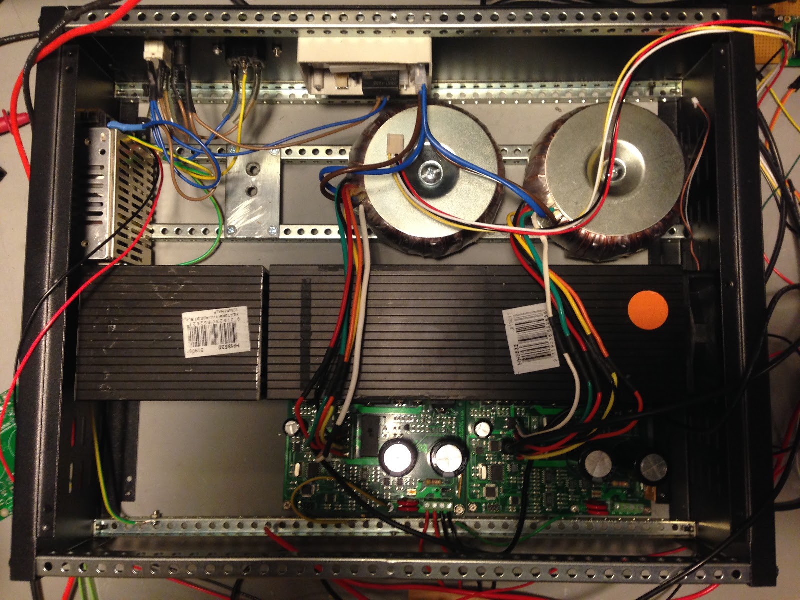
So I started looking at the power supply and not only had it been removed but a repair had been attempted. What I found was that
  • The main switching transistor (on the big heatsink) was missing.
  • A Zener diode (ZD1) near the switcher was missing
  • A diode was missing
  • The main filter caps had been replaced (and with 250V rated ones although this turned out to be ok - see below).
  • The fan was missing
I approached the seller about this. I didn't really want to send it back as then I lose the shipping twice. We negotiated a reduced sale price and I notched this up to experience.

He is still selling stuff though and he has another advert with the same misleading text and similar blurry photo. The seller is mannd1deborah Here is one of his dodgy ads. You've been warned!

The Damage

The power supply seems to have suffered a pretty catastrophic failure of the main switching transistor. There is a significant scorch mark on the PCB around it and a few associated components have been removed by whoever attempted the repair.


A few of the tracks lifted in the area around where it got hot. Also on the secondary side there is a diode with some adjacent heat damage to the board. The fact that the fan was missing made me think it must have failed and caused the power supply to overheat.


Missing Parts

I downloaded the component level service manual from Keysight for the unit but unfortunately it doesn't include the schematics of the power supply. The power supply is labeled 'SMP-43DP' in the silkscreen and 'SMP-43DL' on the bottom of the metal plate that holds it and is made by Delta.

I tried contacting Delta but they said they had no records on it and told me to contact Keysight. I contacted Keysight and got nothing. In fact you can buy the power supply as a spare part but when I asked about it my email was never responded to.

In the past when I repaired a switch mode supply like this the first thing would be to look up the datasheet for the main switching controller IC as often the circuit is very similar to the typical one listed in the datasheet. In this case however the unit is old enough that it doesn't have an IC controlling it.

My first assumption was that the main transistor would be some kind of switching MOSFET.  I asked on the HP/Agilent Test equipment yahoo group and someone pointed out that the zener diode going to one of the transistor legs is connected to the positive rail of the main filter caps (i.e. 340V) so that wouldn't be much good for clamping a gate. The conclusion was that it must be a bipolar transistor.

Also the guy on the yahoo group explained why the capacitors are only rated for 250V - the thing is there are four of them and they are not all in parallel but the arrangement is more complicated. It turns out the supply contains a circuit for detecting the mains input voltage and if the voltage is around 100-110V it will use the bridge rectifier in a configuration where it doubles the voltage (there is a good description of how this works here). The upshot is that if the supply is running somewhere like the US where the mains voltage is 110V then the point between the pairs of capacitors is .at the input voltage but in Europe or Australia then the caps in series have 220/240V across them (in total).

There are a bunch of youtube videos where people teardown or repair these counters (such as this one and this one). The problem is that all of these have a different version of the supply. So even if I could see the parts in question then they will be different. Someone called JF2014 even posted a schematic on the EEVBlog of a 53131A supply but it too was for the other version).

Subterfuge and Guile

So then what are the missing parts? So I started looking at transistors rated for 1000V VCE and ones that could handle a couple of amps. What worried me is that guessing might result in a charred mess.

I found a guy selling a replacement power supply for a 53131A on Amazon and US ebay (doesn't ship internationally) which was the same version as mine. He wanted more for the supply than I paid for my unit (and shipping) so it wasn't an option.

I contacted him and asked very nicely if he would read the numbers off the big transistor and the adjacent zener diode. After a couple of emails back and forward (including some pictures and arrows) he said the transistor was a BUV48A. Winner! I didn't have the heart to ask him to go back and get the numbers off the zener however.

So luckily this transistor is available on RS - not cheap but available. So good news as now I have the most critical part covered.

Other Parts

After much googling I figured out the fan is a Fonsan Delta DFB0412M. Believe it or not I found some parliamentary expenditure report that listed 53131A and the fan part number. Since then I found a fair bit of discussion about using quieter fans and Gerry Sweeney modified his counter to switch off the power when the switch is clicked. Anyway I found a seller on ebay that sells the original fan and ordered one (again - not cheap).

So the missing diode was likely to be exactly the same as the one next to it which was a RFP203 - a chunky 4A, fast recovery diode intended for swithmode supplies. I found a suitable (i.e. fast and high current handling capability) replacement and ordered one. The diode on the secondary side was much smaller and was in a tight spot so using the chunky diode wouldn't work. I ended up just ordering a EGP20D.

Zener Diode


So now I only had one part to work out and that was the zener diode. The only thing I could think of was to draw out the circuit and try to work out what voltage rating it needed to have.

Initially I started drawing the entire circuit but this was pretty time consuming and it occurred to me that I only needed to work out the part near the switching transistor.

I sketched out the following:

While probing around to draw the circuit I noticed a short in places where I didn't expect to see one. It looked like the short was Q1 so I removed it from the board and sure enough it was dead. Unfortunately it is a discontinued Sanyo part (2SD1247) so I ordered some NOS from Greece on ebay.

There are a few interesting things here:
  • The frequency is determined by the resonant frequency of the transformer primary and other capacitors
  • The feedback is provided not by an opto-coupler but by a transformer! Talk about old-school.
The problem was I couldn't see what would need the voltage drop of ZD1. It looked too me like if you removed ZD1 the 47K resistor (R6) would limit the current enough that it would all work. I put the circuit into LTSpice and by measuring a few inductances and capacitances using my LCR meter I could get the circuit to run under simulation (even with the wrong transistor models). The problem is it didn't seem to make a big difference if I made the zener 10V or 200V.

I put up a question on EEVBlog but after a couple of days nobody replied. I then put up the same question on the HP forum and I got an answer - basically the zener prevents the supply from starting if the voltage on the capacitors is too low. So if instead of 110 the input voltage was 80V or if it was 180V instead of 220V this would prevent it running. Basically the zener needs to be rated for around 180V to prevent the circuit starting.

Putting it all Together

So the 180V zeners arrived from RS, the transistors from Greece and the fan was here. I had everything I needed and put it together.

I attached the supply to my isolation transformer, stood back and switched it on - I was elated to see the fan spin as this must mean the primary is switching! I did some more testing and found the 12V wanders a bit if the 5V is under no load (I used my dummy load to load up 5V as it is the highest current output). Otherwise all the output voltages were very good. 

Crossing fingers and toes I connected it up to the counter and it worked!


I haven't checked the performance specification but it seems very close. The output of my signal generator measures to within 1Hz up to 20Mhz. They can't both be out by the same amount!

The annoying thing is the fan run constantly even when the device is off. The screen is just a little dim but quite usable. Overall this turned out to be a good score and another valuable learning exercise.

Lab Power supply Pi Control and Auto-Cal


The Raspberry PI power input control boards arrived and I assembled one and tested it. I built a wiring harness for the fan and for the temperature sensors and attached the temperature sensors to the heatsink. I built the final channel and put it in the case.

Also control interface got re-oriented and got a much needed speed up, I figured out how to start the software when the operating system boots and I built some code to automatically calibrate each channel and store the calibration values in EEPROM.

Raspberry Pi Power Control Board


So the power control board came back and looked pretty good overall. One problem was that the holes for some of the connectors were a bit tight. I tried slightly reaming out the holes but stuffed up one board in the process. Then it occurred that I could just file down the pins of the connector and this worked really well.

Oddly the female header connector for interfacing with the Raspberry PI isn't stocked at my local electronics store and so I had to order one from RS. This one connector however cost $5AUD which is totally silly.

I built a small board for the LED and power switch. The idea is the board is mounted on stand-offs that are just tall enough for the switch to protrude through the front panel. The problem was that there wasn't enough space for the connector as it has to mount on the component side (same side as the switch and LED) as it is a single sided PCB. To get around this I just soldered wires directly to the board and hot-glued them for mechanical strength. I screwed standoffs onto the board and hot-glued this to the back of the front panel. This works Ok overall.


Otherwise everything fitted nicely and worked very much as the proto-type did. Pretty happy with it. Only thing is the LEDs are a bit bright.

Temperature Sensors

In hindsight I really wish that I had integrated temperature sensing into each PSU channel and read the temperature via the channel interface.

Instead I built a wiring harness for the temperature sensors that basically wires them all in series. The termination resistor for the temperature sensor's 1-wire bus is on the Pi Power board so this is pretty simple.

The not-so-nice part is that then I have to mount them on the heatsink which involved hot-glue and a lot of cursing. What is worse is that they don't make very good thermal contact so the readings aren't the best (the temperature readings are much lower than what I get with a probe or non-contact thermometer). Still it will do for fan control purposes.

The reading rate of the sensor is quite low. I integrated this into the software by having it only read the temperature every few updates. I added a simple algorithm for fan control that basically ramps up the fan when the temperature goes over 30C. The fan hits full speed at 40C.

Starting the GUI

I didn't realize that Kivy doesn't actually run under X-Windows but basically directly accesses the frame-buffer. As a result I can use raspi-config to change the boot options and not start X-Windows. Now when I run the Kivy application from an ssh session is starts as before and works fine.

I created another daemon script (see previous post) for starting the power GUI. One change I had to make was that for some reason if I run the app as root the app will run but it doesn't respond to user input. A small change to the script allows it to run as the pi user and we are all good.

Now the Raspberry PI will boot and then will go straight into the power supply application.

Here is the daemon script (which again was derived from a template).

#!/bin/bash

### BEGIN INIT INFO
# Provides:          labpower-gui
# Required-Start:    $remote_fs $syslog
# Required-Stop:     $remote_fs $syslog
# Default-Start:     2 3 4 5
# Default-Stop:      0 1 6
# Short-Description: Starts the Lab power supply GUI
# Description:       Starts the Lab power supply GUI
### END INIT INFO

# Change the next 3 lines to suit where you install your script and what you want to call it
DIR=/home/pi/LabPSU/LabPowerSupplyCtrl
DAEMON=$DIR/MainWindow.py
DAEMON_NAME=labpower-gui

# Add any command line options for your daemon here
DAEMON_OPTS=""

# This next line determines what user the script runs as.
# Root generally not recommended but necessary if you are using the Raspberry Pi GPIO from Python.
DAEMON_USER=pi

# The process ID of the script when it runs is stored here:
PIDFILE=/var/run/$DAEMON_NAME.pid

. /lib/lsb/init-functions

do_start () {
    log_daemon_msg "Starting system $DAEMON_NAME daemon"
    start-stop-daemon --start --background --pidfile $PIDFILE --make-pidfile --user $DAEMON_USER --chuid $DAEMON_USER --startas $DAEMON -- $DAEMON_OPTS
    log_end_msg $?
}
do_stop () {
    log_daemon_msg "Stopping system $DAEMON_NAME daemon"
    start-stop-daemon --stop --pidfile $PIDFILE --retry 10
    log_end_msg $?
}

case "$1" in
    start|stop)
        do_${1}
        ;;

    restart|reload|force-reload)
        do_stop
        do_start
        ;;

    status)
        status_of_proc "$DAEMON_NAME" "$DAEMON" && exit 0 || exit $?
        ;;

    *)
        echo "Usage: /etc/init.d/$DAEMON_NAME {start|stop|restart|status}"
        exit 1
        ;;

esac
exit 0


Ninety Degree Shift

The original GUI design was based around having the outputs for each channel below the screen. With the big 7" display there isn't enough space below to do this so instead the outputs are beside the screen. So to make this more usable I re-oriented the display to be in rows instead of columns. This way the details of each channel roughly lines up with the connector. The GUI is still a work in progress. Later I plan to add graphing and maybe a virtual knob to adjust voltage/current.


Speedup

Now that I have three channels running I found the GUI painful to use. The problem is that when you hit the voltage/current set buttons it can take quite a bit for the dialog to appear. This is because the code is sequentially cycling through and reading back the voltage/current/status from each channel and as the interface to the channels is relatively slow (115200 baud) this takes time. If you hit a button at the same time the code is running through some updates you have to wait for them to complete before it will respond to the button press.

I thought about how to speed this up and I thought perhaps I could increase the baud rate or even create a new 'uber' command that fetched all the relevant details back within a single exchange. The problem is that even if I do this the ADC is relatively slow and so the command will take some time to complete. I don't need it to be super-fast but I just want the GUI to be responsive.

I found out that python has quite good support for threading out of the box. I modified the code that manages each power supply channel so that it kicks off a thread that constantly fetches the status in the background. The thread reads the status into a bunch of class members which can then be read by the GUI whenever it updates. This way the updates to the three channels can happen concurrently and the GUI is never tied up.

The problem then is that if the GUI requests a change (say to set the voltage or whatever) while the thread is running, the commands generated by the thread and by the GUI will clash. Instead when the GUI requests a change the power supply channel code puts the request into a queue. Each time the thread goes round to do an update it checks to see if there is a command to process and sends that to the channel first before fetching the status.

To make accessing the status held by the power supply channels thread safe I created a small class that contains a mutex and which holds a copy of a variable. It has a setter and a getter method and it copies the value passed in and returns a copy on the way out. It locks the mutex before accessing the data in both directions to avoid problems with concurrent writes and reads.

I also changed the channel code so that when a dialog comes up it stops all the updates (not just the updates for the channel being commanded).

So now the dialogs still come up a little slow but when they do come up the buttons are responsive. The update speed of the GUI is fine and overall the GUI now works quite well.

Auto-Calibration

The tables of points used to calibrate the ADC/DAC readings was stored in constants within the code. I generated these constants using a small python script that commanded the supply to go through the full range for voltage/current outputs while reading back values from a LAN attached multimeter.

The problem with this is that each channel needs a different table of values and I don't really like having different firmware images per board.

The logical thing is to update the firmware so the table of points is stored in EEPROM and provide functions to read/write these values. The python code for stepping through the output range can then be integrated into the Kivy GUI.

This turned out to be a bigger job than I hoped. I had to:

  • Create a class for reading the linearizer data from EEPROM
  • Update the Linearizer code so it can be setup after construction.
  • Add a command to set the number of points and to set each point in the linearizer table for the Voltage ADC/DAC and Current ADC/DAC
  • Modify the Kivy GUI to pause everything, allow the GUI to directly (not via the thread) command the channel to move through each point and to communicate with the multimeter to read-back the voltage. The GUI needed a progress bar display and needed to allow the user to enter the hostname/IP of the DMM.

Running out of RAM on the Microcontroller


The first thing that happened was I loaded the code into a channel and it basically was non responsive. After some poking and the addition of text debugging I figured out that the firmware ran out of RAM (the ATMEGA328P only has 2K)

I was able to figure this out by using this bit of code for working out how much free RAM there is based on the stack address

int freeRam () 
{
    extern int __heap_start, *__brkval;
    int v;
    return (int) &v - (__brkval == 0 ? (int) &__heap_start : (int) __brkval);
}
printf("Free ram is %d\r\n",freeRam());

This was I could pepper the code to see where the RAM was being consumed and how much. Because of the way the interpreter works, most of the RAM is allocated when the main object is created.

My biggest problem was that in addition to the tables for each of the ADC/DAC linearizers I had static constants containing default tables (in case the EEPROM is blank). Static constants end up using both EEPROM *and* RAM. The compiler allocates RAM for the constant, reads it from EEPROM and copies it into RAM. I changed the defaults to be dumb one point tables and this brought the usage down considerably.

The other thing was I included a pointer to the LabPSU object in every command. Assuming pointers are 4 bytes, as there are 26 commands this equates to quite a bit of RAM wasted. I changed the code so the pointer is passed in during parsing and recovered loads of RAM.

The final change was I switched from 32 points to 16 points for the tables and this was enough for the code to run reliably.

Next Steps

There are a few things I'd like to add to this project but none of them are urgent. Furthermore I've been working on this for nearly two years and I feel like it is time to do something new for a while. So for now I am calling this complete although I might add some new features in the future.

The future list includes:
  • Virtual onscreen knob for adjusting voltage/current
  • In addition to displaying the current/voltage/power a graph mode where you can see a graph of the output current/power
  • A curve tracer mode for plotting IV characteristics of LEDs etc
  • Maybe a battery discharge simulator.
Here it is on my bench in action.


Tuesday 27 September 2016

My Ruby Notes

So I needed to learn Ruby. Mostly because we are going down the Puppet route at work and so I needed to work with a library that was Ruby based.

At first glance it looks very Python like but not. I thought I'd write up my notes here as I read (both for my own uses and for others in case this is useful).

So my background is as a C/C++/Java developer so I tend to look things in terms of that or the other languages (Perl, Python etc) that I have worked with. Please read these notes with that context in mind.

Comments

  • Hash (#) and multi-line wrapped in =begin and =end. The begin/end must be at the start of the line

Identifiers

  • One starting with lower case or underscore are local? (local to the scope) Weird. Otherwise what scope?
  • Can end in ! or ? or =  This is odd also
  • Object data members (instance variables) begin with @
  • Static (class variables) begin with @@
  • Variables starting with $ are global.
  • Variables in caps are constants
  • self is like self in Python or this in C++ I think.
  • nil is like Java Null
  • true/false are lower-case - seems odd as I would expect them to be FALSE and TRUE. Or $FALSE and $TRUE. Hmm
  • Long list of pre-defined $ variables. See here. Very perl like.

Literals

  • Strings quoted with single or double quotes. Can backspace escape quotes as normal
  • There is a weird % delimeter scheme where you can use other string delimeters. So you can say %{This is a string} or $(This is a string). Ok - bye bye readability.You can control interpolation of the string (see embedding expressions below) using a character after %. See here for table
  • (Interpolated string) You can embed an expression wrapped in #{ } inside a string and it will be evaluated and embedded. Not sure when it is evaluated - I assume when the string is elaborated (so probably not overly useful except for strings defined inside the code).
  • (Here documents) You can use the <<END etc syntax from shell to embed a multi-line string
  • Make an array with Array.new or []. Can initialise an array as you expect. Can use %w in front of array to initialize using spaces as delimeter instead of comma. The question is why?
  • Negative indicies index from end of array. God - readability.
  • Can specify a range with [1..5] etc. If you use three dots it doesn't include the end value. Again. readability.
  • Can have perl-like associate arrays so { "x" => 1, "y"=>2 }
  • Has concept of ranges like 0..5. Can be floats or whatever but must be consistent. Has triple equals (===) operator for testing if a value is in a range. Handy I suppose.

Operators

  • Has most of the assignment operators of C (i.e. a += 10  or a *= 10 etc)
  • No ++ or -- (like python)
  • Can use comma to do multiple assignments. Yuk. So a,b,b = 1,2,3. Also can assign an array
  • Conditional assignment is interesting x = x || "Default" - will assign if x is nil or false (but not empty it seems). Ditto x ||= "default"
  • &&= is opposite - so will assign only if NOT nil. Why?
  • nil behaves like false to logic exprs. Any non-nil value behaves like true. Very C like
  • There is an and/or as well as && and ||. The words variant has lower operator precedence so goes after assignment. Yuk - use brackets. Bye bye readability

Control

  • Conditionals have values. Ok I suppose. I think.
  • The form is if xxx (new line and statements) end. Can use then as separator for single line. What have they got against brackets?
  • There is an unless expression which is basically if not but you can't have an else
  • There is a ternary operator. Of course there is - they seemed to have boiled every other language down to the syntactically most obscure and confusing-to-read elements and included them all.
  • Can use ifs as guards x = 7 if month = 'Feb'
  • Like Moduala II and Ada (I think - God it's been a while!) There is case expression with when for each case. If you say case x you can just say when 22. If you say just case you have to say when x == 22. You say else as the default case.
  • They have while and until as loop constructs. No range iterating or iterating over arrays etc (AFAI can tell)
  •  There is a return statement.

Calls

  • Oh god make it stop. You can call functions without parenthesis. If you want to use the result inside a one-liner you have to wrap the arguments in parenthesis. So result = add 1, 2  is ok but you have to say result = add (1,2).reverse to call the reverse function on the result (ok bad example as you can't reverse an integer).
  • Method definitions are like python so def xxx(params) ... end. Params don't have types and no indication of the return value type. Methods have a value (can be nil).
  • Params can have defaults like in C++
  • Can use * in front of parameter to make a varargs call. If you use * when passing an array it expands the array as arguments (like xargs in shell I suppose)
  • You can use the ampersand & operator in front of a variable to indicate it is a code block.

Scopes

  • As above there is a local, instance, class and global scope. Code that is not in any other scope is in a local scope called the 'main' scope (basically in the scope of the 'main' object). Ok...
  • Umm there is some weirdness about 'procs' that bind to the scope you are in. Not sure what a proc is yet. If you def something it gets a new scope however... So whats a proc?

Procs Blocks and Lambdas

  • Lambda is Ruby are much like Python lambda - tiny functions you can pass around.
  • Procs are a bit different as the content of the proc runs in the same scope as the caller. For example if you use the return keyword in a proc it causes the function that called the proc to return. Also it looks like variables in the scope where the proc was called are available to the proc code. Makes life interesting if the same proc is used in multiple places. Not nice I think.
  • Blocks are confusing but as I understand it they are an anonymous proc. So you can pass a block to a function and have the function execute it. It looks like you don't pass a block as a parameter (like you would a proc or a lambda) and to call it the function uses the yield statement. Again yuk... How do you know if a function can use a block or not?

Dynamic Methods

  • Oh goody - you can dynamically create methods for just a single object
  • Worse - there are calls made on object like method_missing that can be used to dynamically create a method when the method doesn't exist. Have fun debugging that!

Classes

  • Classes must start with a capital (and be CamelCase it seems)
  • Instance variables (i.e. @thing) are ONLY accessible inside the class - so you *must* have accessors
  • There is some weirdness with modifying variables outside a def but within a class. The variables are 'class instance variables' which means they are not a class variable and not an instance variable. Essentially the class is itself an object and they are a member of that but you can't access them using @@. Basically don't do this.
  • You can call a setter method foo= which means you can say this_instance.foo = 10 and it works.
  • There is a attr_accessor for easily creating pairs of accessors.
  • You can make methods private using private keyword private: some_method
  • Private methods are accessible to child classes
  • Private are not accessible to another instance of the same class. Protected ,methods however are
  • Ruby - like most languages these days - only supports single inheritance. So I suppose you can't really define interfaces then...

Modules

  • Like Modula II modules - a namespace basically.
  • One cool thing about modules is you can 'include' them into a class. So you can define functions that refer to class variables and then you can drag those functions into multiple classes as a 'mixin'
Probably much more I can say but this is a start. Hope it's useful!

Sunday 21 August 2016

Lab Power Supply - Raspberry Pi Power Control

So in order to make shutting down the power supply safe for the Raspberry PI, I need to build a soft power-on circuit so that power to the Pi is only cut when it is has completed its shutdown.

In addition I want:

  • A power light to indicate when the standby power is on and when the main power is on.
  • Push button that can turn the who power supply on or off (safely)
  • A 12V supply and speed control for the heatsink fan
  • An interface to connect temperature sensors so we can monitor the heatsink temperature.


Hardware

As discussed previously, the 5V power for the Raspberry PI is provided by an embedded switch mode supply. This will also act as a stanby power source when the supply is off. The main power supply (i.e. the torroidal transformers) are switched using a different circuit under the control of the Raspberry PI (see previous blog on this).

The power switch circuit is based around a P channel MOSFET (Q2) so that initially when power is applied the MOSFET gate is at the supply rail and no power is passed to the Raspberry PI. When the switch is pressed it activates Q3 which pulls the gate low, powers up the Raspberry Pi and actives Q4 which keeps the MOSFET gate low (latches the power on).

When the PI is ready to shutdown it activates Q5 (via the RC network) which turns off Q4 which turns off Q2. The problem is that deactivating the power turns off Q5 and can cause the power to just glitch and turn back on. The RC network keeps the MOSFET off long enough that it won't come back.

The Raspberry PI monitors the voltage at the power switch and will initiate a shutdown if the level goes low (see be

There is a low-side switching transistor that is driven by a PWM signal from the PI to control the fan speed (Q1). The fan is powered from a small boost converter that is running on a daughter board soldered on using a DIP header to the main board. The 12V boost converter is one of these Pololu jobs off ebay. I had to add a diode to the boost converter input as it was causing problems with turn-off and keeping the power on. Also I found out the hard way that a 1N4148 diode was not beefy enough to supply the boost converter.

There is a header and pull-up to connect a string of DS18B20 temperature sensors. These are a very neat 1-wire bus temperature sensor capable of high precision. There is a Linux driver for the Raspberry Pi that makes super-simple to interface. The plan is to add one of these near the pass element on each heatsink and to use this feedback to control the fan speed.


The board is a very and designed to fit onto the raspberry pi GIO header. I took a simple approach in the design and flood-filled the bottom with ground and the top with 5V. The GPIO header is soldered onto the bottom of the board.


Getting the PI to Signal when it is Done

My first approach was to write a little python program that would set a GPIO pin high and to run this when the operating system is about to go into halt state. I modified the /etc/init.d/halt script and added a call to my program just before it calls the 'halt' program but found this didn't work. For whatever reason by the time we get here we can't control the GPIOs from python anymore.

I did some searching and eventually found that there is a way to control the default state of the GPIO pins. There is a set of configuration files in /boot that enables/disables hardware systems. These are read by the kernal at boot and will usually result in additional drivers being loaded but actually you can change the state of hardware using this config.

Some of these files are .dtb files or Device Tree Blob files. There is a compiled (dtc) used to generate these using a dts (text) file. The language is a bit c-like and uses curly brackets to define data as structures.

Initially I thought I just wanted to set the default state of the power pin when the Pi shutsdown but after some digging I found there is a mechanism here to configure a GPIO pin to be set when the PI shuts down - this is basically intended for signalling shutdown to other hardware.

The complicated part is that the device tree is segmented by raspberry pi hardware type and then there is hardware which is available on multiple devices. Some hardware is optional and then you can add custom configurations for hardware. To handle all this they created an overlay system where you can create an overlay dtb file that gets loaded on top of the device tree to implement a specific change.

There is an overlay called gpio-poweroff that does exactly what I want. To enable this you modify /boot/config.and add a line like this (see below). The option after the comma determines which GPIO pin will be asserted at power-off

dtoverlay=gpio-poweroff,gpio=25

There is more details on device trees and overlays etc here

Detecting a Power Button Press

Now we want to detect a power button press from python and when it occurs we want to trigger a shutdown. Here is a simple python program that (using the GPIO libraries interrupts feature) triggers a function when the pin state changes from high to low. The pin state change is caused by the button press.

#!/usr/bin/env python

from subprocess import call
import RPi.GPIO as gpio
import os
import time

# Define a function to keep script running
def loop():
    while True:
        time.sleep(5)

# Define a function to run when an interrupt is called
def shutdown(pin):
    os.system("sudo shutdown -h now")

gpio.setmode(gpio.BCM)
gpio.setup(4, gpio.IN)
gpio.add_event_detect(4, gpio.FALLING, callback=shutdown, bouncetime=200)

loop() # Run the loop function to keep script running

Now we make this file executable to the world.

We want this program to start when the operating system boots so we need to create a daemon for it.

I created a file in /etc/init.d called powerbutton-watcher and it contains this (taken from a template). The script resides in the /home/pi/LabPSU/LabPowerSupplyCtrl directory.

#!/bin/bash

### BEGIN INIT INFO
# Provides:          powerbutton-watcher
# Required-Start:    $remote_fs $syslog
# Required-Stop:     $remote_fs $syslog
# Default-Start:     2 3 4 5
# Default-Stop:      0 1 6
# Short-Description: Watches the state of the power button and initiates shutdown
# Description:       Watches the state of the power button and initiates shutdown
### END INIT INFO

# Change the next 3 lines to suit where you install your script and what you want to call it
DIR=/home/pi/LabPSU/LabPowerSupplyCtrl
DAEMON=$DIR/WatchPowerButton.py
DAEMON_NAME=powerbutton-watcher

# Add any command line options for your daemon here
DAEMON_OPTS=""

# This next line determines what user the script runs as.
# Root generally not recommended but necessary if you are using the Raspberry Pi GPIO from Python.
DAEMON_USER=root

# The process ID of the script when it runs is stored here:
PIDFILE=/var/run/$DAEMON_NAME.pid

. /lib/lsb/init-functions

do_start () {
    log_daemon_msg "Starting system $DAEMON_NAME daemon"
    start-stop-daemon --start --background --pidfile $PIDFILE --make-pidfile --user $DAEMON_USER --chuid $DAEMON_USER --startas $DAEMON -- $DAEMON_OPTS
    log_end_msg $?
}
do_stop () {
    log_daemon_msg "Stopping system $DAEMON_NAME daemon"
    start-stop-daemon --stop --pidfile $PIDFILE --retry 10
    log_end_msg $?
}

case "$1" in

    start|stop)
        do_${1}
        ;;

    restart|reload|force-reload)
        do_stop
        do_start
        ;;

    status)
        status_of_proc "$DAEMON_NAME" "$DAEMON" && exit 0 || exit $?
        ;;

    *)
        echo "Usage: /etc/init.d/$DAEMON_NAME {start|stop|restart|status}"
        exit 1
        ;;

esac
exit 0

Finally to get this to start with the OS I used the following command

sudo update-rc.d powerbutton-watcher defaults


Tuesday 21 June 2016

Lab Power Supply - New Boards, Input Power Control and the Case

So it has been a while since the last update but I've not been idle! The lab power supply is taking shape although there have been a few hiccups. The new boards finally came, I found a hiccup at higher currents and I started some assembly into a case. I designed and fabricated a board to turn on power to the main supply. The problem is that I've been pretty busy so much of this has been done in bits and pieces. I hope I am recording the journey well enough to follow!

New Boards

The new boards look very sexy. They make much better use of space and the layout is more logical. While it still isn't easy to tighten the screws, it is much easier than the previous proto-type. Here it is nearly completed below.


With bated breath I tested it for the first time. I had massive expectations of the new high-precision shunt resistors and... It didn't work. After some head scratching I realized the expensive shunt resistor was 0.1 ohms instead of 0.01 ohms. I changed the amplifier to suit and this work but I also realized that the current limit for this resistor would be around 2A. I gave in, ordered the right resistor and then waited for it to arrive (don't ask how much).

When the right resistor arrived, I fitted it and tested the unit again. I was quite impressed with the current accuracy and overall everything was working well.

Load Testing and Overshoot

While waiting for the replacement shunt-resistor I was experimenting with the simulation and found that I could increase the capacitor in the voltage control circuit to reduce the overshoot. By increasing C20 to 20nF I could completely eliminate the overshoot and not effect the transient performance. I tested this and it did indeed behave this way.


One of the key changes in this version was that I moved the bridge onto the heat sink. I wanted to run some load tests to ensure this was successful.

My dummy load is only capable of 4A, I tried a slightly different approach which was to use a 1 ohm concrete resistor immersed in big cup of water. This worked really well as it takes quite a while for the water to heat up.

I found that with the current limit set over 4.5A that the output would oscillate. I thought it could be the supply is running out of headroom voltage on the capacitor but that wasn't it. I figured out that the additional capacitance I added to control the overshoot was causing the oscillation.

I figured out that if I increase the compensation capacitance on the current control amplifier I could get rid of the oscillation and still have a higher capacitance in C20 to reduce the over-shoot.

This still needs some thought but overall this is looking pretty good. One negative effect of increasing C20 is then the output voltage slew rate is much lower. It can take much longer for the output to hit the set point or for the voltage to recover after an overcurrent limit event. I still need to finesse this a bit but for now I am moving looking at other things.

Other Testing


I also finally got the courage to short the outputs and to verify the current limit behaves correctly and it did. The supply also behaves correctly with the current set to small values (like 10mA) now with the correction to the pre-regulator.

I tested the behaviour of the pre-regulator with a pulsed load. This would still not always recover back to the set voltage - particular in the 15-30 volt range. I ended up increasing the resistor in the peak-detector circuit (R52) to 100K and this worked. The only thing is that now in 30V mode it can get very hot with a pulsed load that drives the output down to low voltages (in the over-current events). In most circumstances this won't happen as either the over-current will lead to a constant state and the pre-regulator will adjust or the over current pulses will be infrequent.


Mains Input

Because the Raspberry Pi must be shutdown and can't just be turned off, I need to control the power to the Raspberry Pi and the main transformers separately. The ideas is there will be a permanent 5V supply but the main transformers will only be turned on when the Raspberry Pi is up.

I also need to deal with the inrush that occurs when the unit is powered up as three torroidal transformers feeding an array of capacitors will suck a considerable startup current.

I really need to keep this circuit stupidly simple, I don't have an isolation transformer or a differential probe and I don't want to have to debug it if I can get away with it. Also I can't proto-type this circuit on bread-boards or matrix board as - well that would be dangerous.

I came up with the idea of using two Solid State Relays (SSRs) and a power resistor to turn on the main supply and control in-rush. One SSR turns on the 240V supply via a power resistor and the second SSR shorts-out the power resistor. Both are activated by the Raspberry Pi when the software starts.

I use simple NPN transistor to switch on the relays using the 5V supply. The Pi generates 3.3V signals which activate the transistors. I designed the circuit to have an input and three output connectors so most of the mains wiring is routed through the PCB. Here is the circuit (below)

Main Input PCB

I didn't want to wait three weeks for this PCB to come back and it is quite simple to implement as a single sided board. I thought I would try my hand at etching the PCB at home.

I bought a small ($3) 80x50mm box from Jaycar that would hold the circuit. I'd have to either not use the lid or cut a lot of holes in it but I thought it would be better to put the mains circuit in a box. For starters it makes it harder to accidentally touch the live circuit and the box insulates the metal case from the PCB.

I designed the PCB to fit comfortably in the box. It looks like this:


The main things were to keep the power tracks fat and to place the low-voltage circuit as far away as possible from the main circuits. It was harder than I thought to get it to all fit in the box but I got it to work in the end.

Etching PCBs at Home

My plan was to use the toner-transfer method to etch the PCB. I don't have a laser printer at home so I used the local Officeworks store.

I printed the bottom side artwork as a PDF and asked KiCAD to include dots for the drill locations. Initially I flipped this but then realized that was wrong. The toner transfer process ends up flipping the artwork so this cancels the flip caused by the bottom side being printed when viewed from the top.

I copied and pasted the PCB so there would be four artworks per page and asked Officeworks to print me a few copies onto shiny (photo paper). I only really used one page but they were 35c each and I felt sorry for the lady as she had to fight the machine to put photo paper into the black and white laser copier.

I cut out the board artwork from the paper, cut out a piece of PCB the correct side and used sticky tape to keep the artwork aligned with the board.  I used a laminator to heat the paper so the ink would transfer but I found even running it through the laminator a few times was not enough to transfer the ink reliably onto the paper.

I tried using a clothes iron and while this transferred the ink quite well it also melted the tape I used to hold it on (but that doesn't matter I think). The problem was that when I peeled the paper off it tended to take the print with it.

I did this a couple of times with no success. I had an idea that if I softened the paper with water it might leave the ink behind. This worked really well. I soaked the paper and gently wiped it off the board while leaving the ink behind.

I etched the board in Aluminium persulfate and the results were excellent! The image below shows the board as it came out of the etchant.


Drilling the holes was not much fun. I bought a set of fine drill bits that have larger shanks so you can hold them in a normal chuck. I used to drill press to do the drilling and mostly the holes lined up. The bigger holes for the power connectors wandered for some reason and some ended up a bit crooked. No matter overall.

Here is the board assembled


And here is the solder side.


Raspberry PI GPIO and Python

Controlling GPIO pins from Python is relatively straight forward. Initially I stupidly followed some guide that told you to install an ancient GPIO RPM which required the python program to run as root. Once I figured out the newer versions don't require this life got better.

You basically have to add an import and then setup the GPIO pins. You have to choose the naming scheme for the pins you are using between board and the naming scheme of the Broadcom chipset (as the pin names change between versions of the PI). Then you can set or read the pins. In addition I found a 'cleanup' method that resets the pins back to what they were when you started. I added a 'finally' exception handler to do this when the program exits so the mains is not left turned on.

Here is a summary of the code (some bits omitted).

import RPi.GPIO as GPIO
...
def setupIOs():
    print "Setting GPIO 23 and 24 to outputs"    GPIO.setmode(GPIO.BCM)
    GPIO.setup(23, GPIO.OUT)
    GPIO.setup(24, GPIO.OUT)

def turnOnSupply():
   print "Enabling 23"   GPIO.output(23,True);
   time.sleep(1)
   print "Enabling 24"   GPIO.output(24,True);
   time.sleep(1)
   pass

def turnOffSupply():
   print "Enabling 23"   GPIO.output(23,False);
   GPIO.output(24,False);

if __name__ == '__main__':
     try:
        setupIOs()
        turnOnSupply()
        LabPowerSupplyCtrlApp().run()
     finally:
        turnOffSupply()
        GPIO.cleanup()

Case

At this point it is time to start figuring out how this thing will look when it is finished. With the new wide but shallow boards I figured out I can make it all fit with a depth of around 300mm and a width of around 420mm. The Raspberry Pi touch screen needs about 130mm.

I found that one of these 3U rackmount cases from Jaycar would pretty much do the job.

The case is built from these rails that look like meccano pieces as they have holes all the way along. The top, bottom, front and back can be unscrewed and the case is held together by the sides and rails.

They provide four extra rails so I decided to use these to support the transformers and the heatsinks. I made small steel plates that screw to the rails and that have a hole for a bolt to support the transformer. I have round metal plates and rubber protectors that I can use to bolt the transformers down. The plates were made from some bracket I bought from the hardware store (Bunnings). This is what they look like in the case (excuse the messy wiring in the way).


I cut holds for the IEC connector, power switch and fuse into the back plate. I drilled holes through the back plate for the small box that holds the power input PCB and mounted that. The PCB just clips into the enclosure.


The I drilled and tapped the heatsinks for the components from the power supply. I figured out that if I measure, drill and tap the holes then screw the components on and then solder them to the board I can get them to line up perfectly. I drilled and tapped holes in the bottom so they could be screwed into the rails and the rails screwed into the case. I fitted a 12V fan onto the end of the heatsink channel and there are enough holes in the case sides that this will work.

I only had two of the long heatsink channels so I bought a third. I cut this channel in half using a drop saw. The cutting worked surprisingly well although did fling aluminium all over my shed. So now I have the big heatsink with two channels and a smaller one for the third channel.


I needed a 5V supply that can deliver 2A to feed the Raspberry PI. I found a Traco supply on ebay at a reasonable price and mounted that to the side wall. Here is the supply:


The 5V supply is tucked behind the heat-sink on the left of the case.


Here is the overall layout of the box at the moment.


Only two channels have been assembled right now and I have two transformers setup. I had to extend the transformer wiring to make it over the heatsink to the PSU boards but that went Ok.

The protective ground is a problem as the black powder-coated plates are pretty non-conductive. Currently it is organised as follows:
  • The ground comes in and ties to the transformer rails where splits to ground the 5V supply and another ground wire goes forward to the front rail.
  • Each of the power supply channels connects to the front rail ground
  • There will be a ground binding post on the front panel connected to the front rail.
At some point I might scratch off some powder coating to ensure the sides and front/back are electrically connected to ground also.
Currently I have cut the hole for the Raspberry PI in the front panel but I think the only practical way to mount it is double-sided tape. The centre part of the display including the rapberry PI itself fits through the hole and the thin edge of the glass display will mount to the front panel with foam double sided tape.
I don't want to do this until the front panel is completely ready as otherwise I can't drill or work with it. I still need to drill holes for the outputs and for the soft-power switch and indicator LED.

Next Steps

I currently have the Raspberry PI running outside of the case with leads going back in for the USB connections to the channels, the 5V supply and the control signals for the power input.

I need to design the soft switch circuit that allows the PI to switch itself off when it is ready and the fan control circuit. I also want to build temperature sensing for each of the channels so the PI can control the fan.

We are getting close though! It is starting to look like something you might have in a Lab!

Monday 25 April 2016

Lab Power Supply - Board Redesign

So in the last post I was at the point where I felt I had ironed all the faults out of the current design and felt it was time to go for a new board. Since then I rolled all the changes back into the schematics and designed a new board that integrates all those changes.

Schematic Changes

So I will go through each section of the schematic, list the changes and then include the updated schematic.

Power

In this section I made the following changes:
  1. I added a diode across the relay to suppress back-EMF when the relay is switched-off.
  2. I changed the 24V LM317 to be a TO-220 package as the surface-mount version was getting too hot.

Pre-Regulator

In this section I made the following changes:
  1. A buffer for the Ioutmon (U14) and Voutmon (U7D) signals to stop them affecting each other through the summing amplifier. This was causing the voltage to vary under load and causing incorrect current readings at low currents.
  2. A peak-detector (D12, C28, R52) to slow down the decrease in the pre-regulator when the voltage drops. This helps stabilize the output when a pulsed load is driving the system into current limit
  3. A minimum voltage of 0.6 + 3.3V to the pre-regulator (D13, D15, D14, R57). This prevents the pre-regulator going down to zero when the output voltage is very low (for example if you set the current limit to a very low value like 20mA)
  4. A bypass capacitor for U7 (was missing from previous schematic).

Post Regulator

In this section I made the following changes:
  1. The orientation of Q8 was corrected (collector and emitter where the wrong way round due to a footprint change when I changed the component model).
  2. The differential amplifier measuring the output voltage was changed to use 100K resistors and the compensation capacitor was reduced to 4.7pF. This increases the impedance of the amplifier inputs but then the compensation had to be reduced to maintain the same response time.
  3. I removed the four terminal voltage sensing. This wasn't stable and I didn't want to mess around to fix it so for now I am not supporting sense terminals. I will still sense the voltage at the output terminals but you can't connect sense wires to an external load.
  4. The MOV output protection was changed to just 2 MOVs. This is as a result of the change to only have two terminals instead of 4.
  5. The current sense resistor was changed to the Vishay VC1625. While the tempco and accuracy of the Welwyn OAR3 resistor was fine, the thermoelectric effect wasn't. I decided to go with a higher precision four terminal current sense resistor.

PCB Changes

I have been struggling to find a case that will house the project and then the recent discovery that I needed to put the bridge rectifier on the heatsink led me to re-think the problem. In addition to the bridge I need to include another TO-220 for the 24V supply which means I need to make the board much wider.

The heatsink I chose is 254mm wide (10") so there is no option to put three modules on one heatsink. I figured out that if I can reduce the length of the board to below 100mm the project will fit comfortably fit inside a 3U 19" rackmount case. 3U gives me 130mm of height for the Raspberry Pi touch screen which leaves around 30mm of height for binding posts.

The 19" case however is 480mm wide which gives me lots of space. I realized that if I got another heatsink and cut it in half (so 125mm wide) I could fit this in the case also and still get three channels.

Layout Changes

Having the bridge on the back edge makes some things a bit tricky. The bridge needs to be near the relay, the pre-regulator MOSFETs, the capacitors. The VCC bridge also needs to be nearby also but this creates a problem if the power connector is at the edge of the board as some traces would need to be router right over the other side to get to the internal voltage regulators.

Instead I put the internal regulators (for VCC, 5V, 24V) on the left side, the power connector, relay and bridge in the middle and then the pre-regulator MOSFETs and output MOSFET toward the right.

The pre-regulator circuit (except for the opamps) is at the top right near the pre-regulator MOSFETs. The bulk capacitors are between this and the output.

The analog section is at the front near the middle and then the digital section is to the left (section with ground plane). The USB section is below the internal regulators and behind the other digital sections. It wasn't practical to put the USB connector at the edge of the board so this too is in the middle nearer to the power input.

I also used 4mm traces for the heavy current tracks which allowed me to make the board quite compact. 

This worked quite well overall as none of the power traces are very long, the analog bits of the digital section are close to the analog section and the analog section is close to the negative output (which is the ground point for the circuit) and the sense resistor.

The layout is much more dense than before so there are a few more vias. The control lines for the relay transistor, the VCC voltage control and the signal that controls the pass transistor were particularly difficult to route.

I was able to fit nearly everything in with 80mm of width but I couldn't figure out how to rout the Vrelay and Vsetplus lines. I ended up adding an extra few mm of width so the board is 128mm instead of 125mm. This will have a negligible effect except that there will be a slight overhang off the ends of the heatsink.


Here is how the board looks in 3D - not all parts have models.


Other layout corrections:

  1. The ground routing for the analog and digital section all comes off one track that connects right at the sense resistor. Before some of the grounding came off an earlier point on the heavy-current ground path and this created some voltage differences.
  2. The PTC was placed further from the sense resistor to avoid temperature induced errors.
  3. The placement of the capacitors for the AD7705 crystal were too close so these were placed a bit further off.
  4. A bit more space was added between the pass transistor and the pre-regulator MOSFETs to allow the aluminium dioxide insulator pad to fit.

Footprint Changes

  1. The MOV footprint was mirrored before (made sense from bottom of board). This was corrected.
  2. The PTC footprint was mirrored before. This was corrected. Also the footprinted suggested by the manufacturer had the feet too far off the axis of the part so I reduced this a bit to make the part fit more comfortably.
  3. The MCP2200 footprint was the wrong width and this was corrected
  4. The AD7705 was changed to be the SOIC footprint as I got some of these cheaply off ebay.
  5. The pads for the main capacitors were too small. I added bigger pads for better mechanical strength.
  6. The LM317 used for 24V rail got too hot as a surface mount component so this was changed to a TO-220 part.

Next

So I have ordered more boards from Seeed studio and am waiting for these to be manufactured. Next step will be assembling and testing the channel on the new board.