Friday, 15 August 2014

Tektronix 475 Triggering

Triggering

Unfortunately the trigger on my scope still doesn't work. There is a trigger delay knob you can use to delay the sweep after the trigger. If I set the scope for auto triggering (so it sweeps anyway even when it doesn't have a trigger) and then use the delay knob I can sort-of kind-of get the waveform to stay still. And it looks really good when I do! I like this scope!


I really want to fix this scope now!

Ok so I pick a mid-point which is just after Q526, I set the trigger source to channel 1 and connect a signal to the scope. I can see the signal in auto mode but in normal mode I can't get it to trigger. There is a signal there but it is very weak (less than 10mV). So then I pick a spot in front of the two JFETs and sure enough I have a good signal there. Ok we have a neighbourhood!

The base of Q526 has a signal so then I turn it all off, pull Q526 and put it in the transistor tester. The transistor tester tells me it is a resistor. I check the BE and BC junctions with the diode range on my DMM and they look wrong.

Q526 is a 2N4258 PNP switching transistor. Not really sure why they picked this. I have some 2N2907s on hand as I was going to replace the one in the channel switching logic. I decided to give it a go and start up the scope again. Ok! now I have a signal at Pin 3 of the U520! But still no trigger :(

When I hit trace view before I got nothing but now I do see the input waveform but it is pretty dirty and big. The voltage and (as far as I can tell) the waveform matches the pictures in the scan of the service manual I have. So why no trigger.

The manual says I should see the trigger signal on pin 8 and 9 but I am not seeing anything. The voltages are a bit off (13.4 instead of 14.6). The voltages on some of the other pins are a bit off too.

As luck has it the scope has two trigger circuits and they are pretty much identical. Oddly the B trigger seems to have the same issue with the source follower circuit so I replace that transistor too. Strangely the output of that chip is also silent even after doing this. I decided I will swap the two chips and see what happens but this has no effect - they are both still not working.

Someone on the Tektronix forum asked what the bias on the input to U520 was like but that looked Ok.

I tried pulling one of the transistors after U520 to see if there was something loading down the output but this had no effect.

When I scope the tunnel diodes I can see the auto trigger pulse happening so I think they must be fine.

I'm a bit stuck. I really suspect these custom Tektronix paraphase amplifier chips (U520 and U720) are stuffed. Any ideas would be welcome.

Tektronix 475 Channel Selection and Channel 1 Problems

Channel Selection

So now the scope is sweeping but not triggering. I also noticed that no matter what channel switch I select it always shows channel 2 and decided to tackle this next.

The circuit is thankfully mostly digital and based on 74 series logic. The only quirk was that the VSS line was at -5V and VCC was at ground. So logic high is zero and logic low is -4.8V


There is a dedicated channel MUX IC that switches between the different channel input and then the logic decides which channel to display. There is logic to switch between channel 1 and two on the sync pulse for alternate mode and there is a 2MHz oscillator made up from a couple of capacitors and some NAND gates that swaps between channel 1 and 2 in 'chop' mode.

There is a transistor configured as a voltage regulator to generate the -5V and -5.7V used by the logic from the -8V line. The output was a little off and the -5 was more like -5.7 and the -5.7 was closer to -6.4. I tried swapping the transistor but it didn't change.

The outputs of the flip-flops control the channel selection lines on the MUX. These really didn't look right - instead of being near 0 or around -5V they were at around -1.5V. I checked all the resistors to look for a short but no luck.

74 series logic is cheap and easy to come by so the next day I bought replacements for the 7474 and the 7400s. After replacing the 7474 I still didn't have channel selection but the outputs of the flip-flops now looked like sensible logic levels. I decided the output of the 7400 in the chop/alt circuit was off so I just replaced all the 7400s. Thankfully I noticed that U330 is upside down compared with the other chips on this PCB (pin 1 is on the right). Now I can change channels! The other interesting thing was that now the -5V and -5.7 volt lines were the correct voltage.

The alt mode also worked and it displayed two waveforms. Chop however didn't. I looked at the input to U330B and there was no signal from the oscillator. I checked the voltage at the input to U330A and I noticed the -5.7 was present. Weirdly, just touching the legs of U330 with the DMM caused the oscillator to start running. 

Looking at the circuit I actually don't understand how this works. The resistor divider network on pin 12 I thought would set it to low (-5V). When the chop switch is closed pin 1 and 2 go low which brings pin 3 high which brings pin 13 high. But as 12 is low this won't effect 11 and so won't start oscillation.

As I changed both 7400s together I thought I would take a punt and put one back in and see what happens. The first one I put in was the one that used to be U340 and it didn't work at all - the outputs were at -1.5V (not high and not low). When I put the one that was originally U330 it worked! Alt, chop and everything now worked. I still don't know why. I have to assume something about it being 74LS changed things but again I don't see how it works in the first place.

Channel 1

So now when I move the vertical position of channel 1 and 2 the right trace moves and if I am in channel 1 then the channel 2 position has no effect etc. If I connect a signal to channel 2 I can see it on the scope! Its a mess as trigger doesn't work but it is definitely progress. I get nothing from channel 1 however no matter what I do with the knobs.

There are two metal cans at the front of the scope that contain input attenuators. The white boxes below are the attenuators. Apparently they are a ceramic hybrid and are frequency compensated so they attenuate by the same amount across the scopes frequency range. There are a series of tiny gold switch contacts which switch in or out each attenuator and the switches are engaged by pins that poke up from this barrel attached to the volts/div knob below. In the photo below you can just see the first two switches although these ones are the AC/DC/GND switch contacts. The silver input capacitor is visible at the top.


I knew channel two was working so I attached a scope to the output of the attenuator block of each channel and compared. The output from channel 1 was very low. The attenuators are socketed so I carefully removed each of them one at a time and used a piece of paper soaked in Isopropyl Alcohol to clean the switch contact. Essentially you turn the knob until the switch opens, put the paper under the switch and then turn the knob to close the switch. Then you carefully(!) move the paper around to clean the contacts and pull it out. This got the signal shown on the test scope back to something reasonable and now the signal didn't change so much when I moved the knobs.

When I turned the scope on the trace for channel 1 was still a straight line. I then assumed I had an electronic problem. The vertical pre-amplifier is implemented using two custom, hybrid 'cascode' amplifier ICs. A cascode amplifier is two transistor arrangement that offers good bandwith, isolation and slew rate.

As channel 2 worked I could compare channel 1 and 2 to find the difference. I could see the signal at inputs of the second cascode amplifier. I couldn't see any signal at the ouputs. I searched for dead capactors, bad resistors, I tried removing the two transistors following the second cascode to see if the signal would appear but nothing. I even swapped the cascode amplifiers between the two stages but interesting this had no effect - channel 2 still worked and channel 1 still did not. Hmm.. I looked at the biasing of the second amplifier and noticed this was a little different. I noticed that if I set channel 1 to the lowest setting (5mV/division) that I did get a signal although a distorted one.


It turns out there is a second set of switches *underneath* the barrel that changes the volts/div. These ones set the gain for the second cascode amplifier (see below)


I found that I could do the paper trick but from the other side and clean the contacts of the switches underneath. Then I turned it on a again and yeah! A signal!

But still no trigger.

Till next time....

Sunday, 3 August 2014

Tektronix 475 - No Sweep

Still no Sweep


I have to admit that I was hoping that if I fixed the -8V line then the scope would jump into life and everything would work. Alas not.

The trick was where to begin as I know there is a problem with triggering as well as sweep. I decided that even if I can't trigger but I can get sweep happening (in auto mode), then I could move forward. Also, the troublshooting flowchart in the manual suggested I should look at the sweep first.

The sweep circuits in the oscilloscope are quite complicated. There are actually two separate sweep generators that can run at different rates. You can set the scope up so that the 'B' sweep starts a short (and configurable) time delay after the 'A' sweep starts. The cool thing is you can run the 'B' sweep at a faster rate which allows you to effectively zoom in on part of the signal. You can move around the longer trace by altering the delay. Then there is 'A' intensified by 'B' mode, Mix mode and... well I don't know.

The next problem is I've never used this scope - well not in a working state so it took a bit of googling and youtube watching to actually figure out what it is *supposed* to do. For example the time/div knob is marked 'A and B TIME/DIV' and the end of the knob says 'pull' but I didn't see how this worked. It was hard to pull and nothing seemed to happen (I expected it to pull out and click). I turned out you have to pull the knob and then turn it. If you do this it disengages the grey knob from the clear skirt and allows you to set the A and B sweep rates to different values. When you rotate either back so they are on the same speed then they lock together and then when you rotate the knob they both turn.

Sweep Generator

The sweep generator is pretty complicated. The first thing that puzzled me was the the differential amplifiers (Q914, Q926 and so on). To begin with I decided to keep it simple and went looking for a sweep signal coming out of Q956. Sure enough there was nothing there (just a constant 15V). But the sweep circuit is initiated by the 'gate' signal from the sweep logic board. The 'A' sweep seems to get initiated by the main sweep gate coming in on the base of Q902. Looking at TP902 I can see the amplified pulse coming in. Great! That means the fault is somewhere in here... Somewhere anyway...


I noticed that if I turn the sweep rate right up to one of the top three speeds (shortest time per division) that I get a short (about half screen) trace on the scope. I scoped the sweep output while this was happening and sure enough I could see a 'V' which was the sweep reducing the output voltage in a roughly linear ramp.

I still didn't get how this all worked. I knew from the manual it was a 'miller integrator'. Turns out this is pretty simply just an amplifier with a feedback capacitor. The capacitor charges roughly linearly and provides the output ramp. The capacitor/resistor used to determine the time constant are switched in by the timing board depending on where you rotate the time/div knob.

Digging a bit deeper I see that the transistors facing up the page like Q904 are configured to either pass or block the gate signal going to one bit of the circuit. The circuit description in the service manual describes these as a 'disconnect amplifier'. So each sweep generator is a JFET and a transistor together with a variable resistor/capacitor from the timing board. They also have a disconnect transistor that turns that sweep on or off depending on what switches you pressed.

So I choose 'A' mode on the scope and looked at the signal coming out of Q904. I found that it was a bit feeble and scratched my head about why. I figured out the A (lock knobs) button puts 5V to the diode going to the base. I fiddled with the time/div knob and figured out the pulse starts to look like a feeble 1V ramp if I set the time/div to one of the middle speed settings! Ok there is some life in there.

I noticed the voltage at R921 was around 14V. I thought perhaps the capacitor C922 had shorted so I lifted one of its legs but it appeared fine. In fact the circuit was the same without it.

I noticed there was a 1V ramp happening on the collector of Q922 so I followed this through. At the emitter of Q940 is was a feeble bump rather than a ramp. I guessed Q940 might be suspect and pulled it. The transistor tester didn't even identify it as a transistor so I replaced it with a BC547 and tested again. This time the ramp looks a tiny bit better but still no output from Q940.

The trouble is I don't know what it is supposed to look like. I remembered the fast sweep sort-of works so I switch into the fastest sweep rate and looked at the collector of Q1014. The first thing I noticed was the ramp was starting at 15V and going down instead of the feeble 1V. The emitter of Q1022 also showed this ramp. 

The voltage at R1011 swung a lot more. This made me wonder if the JFET Q920 might be toast. On a whim I decided to swap the JFET from Q1010 and Q920 to see what would happen and Voila! The medium/slow sweep now works!

I tried putting Q940 back but no that didn't work. So I had two faults - Q940 was dead and one JFET. The JFETs are a bit unusual so I will have to order some from the US.

I did some more investigation and B sweep is dead as well as the fast sweep. Trigger is still broken and there seems to be some problems in the front-end. I can get some wave form if I wiggle the volts/div channel 2 knob but nothing on channel 1.

So more work to do but some progress!


Saturday, 2 August 2014

Tektronix 475 - -8V still wonky

No Sweep

Ok so the scope has a spot now. I can move it around (a bit) with the vertical and horizontal position controls. This tells me the deflection is Ok but there is no sweep. No matter what I can't get the trigger or ready light to come on so there is a problem with the triggering also.

There has to be something more fundamental that is causing this so I go back to the PSU as I recall the -8V still wasn't quite right.

-8V

The -8V line is now sort-of working after I changed out the bridge rectifier. The odd thing is that it isn't -8V but -8.4V which isn't catastrophic (I don't think) might be causing other things to go wrong.

So I go back to the power supply circuit diagram. I get the transistors being driven by the opamp - the opamp is an error amplifier and then causes the transistors to adjust the voltage until it matches the reference. The transistor with the base pointing towards the right initially stumped me (Q1464) but it turns out this is a 'foldback' protection circuit. It reduces the drive on the main pass transistor if the current is too high. When the current increases then the voltage across R1467 increases with switches on Q1464 which turns down the drive to Q1466.

There is a tonne of current put out by the circuit so maybe this is it. But then I would have thought this would make the output more positive (i.e. less negative) rather than more negative. Doing some voltage measurements the circuit doesn't look like it is in foldback. Hmm


The -8V reference works using a volrage dividor composed of a 50K and an 8K resistor. It uses 50V to create a reference for -8. The voltage between the two resistors is 0V. When I test this with my meter the resistors have 50.0V and 8.4V over them respectively which makes no sense.

I tried measure the resistors but as they are in circuit the numbers don't look right. The 50K looks like 12 and the 8K looks like about 7.6.

Someone suggested the opamps can get flakey over time so I tried swapping this out (they are easy enough to get) but this made no difference. I also swapped the foldback and the smaller pass transistor with some garden variety BC547s but again this had no effect.

The resistors are 0.1% tolerance types and these aren't too easy to get. I ordered a 50K as the measurement on this one was way off.

While waiting for this in the post I gave in one day and decided to lift one leg of the 50K resistor from the circuit and test it (when you have excluded all the likely stuff eh?). The resistor was bang-on unfortunately. I decided I may as well keep going and lifted one leg of the 8K. The weird thing was that it measured 8.4K. Umm hang on - that is my voltage error? Seriously a resistor went *slightly* high resistance? Apparently!

I could get 8.06K 0.1% resistors from element14 so I ordered some and sure enough my -8V supply is now -8.01V. I found an ebay vendor that cheaply sells the 8.0K 0.1% resistors but they aren't here yet. Still -8.01 is well within tolerance. I call that a win!

Finally the EHT multiplier comes in the post!

EHT Multiplier Replacement


So the Tek475 has been sitting on my desk with the vertical board pulled out for quite some time now. Finally the part I've been waiting for came in the post. I was partly hoping to see a red-cross styro-foam eski like you see on the medical programs on TV but not - just a plain box.

I de-solder the connection to the board and undo the plastic nuts but there isn't enough room between this and the metal case to get it out. I loosen off the screws holding the main interface board in including the ones on the power transistors at the back and I am able to bend it just enough to easy the EHT multiplier out safely.

I've undone the cover over the plate above where the metal tube goes and I disconnect the EHT from the plastic connector which is on the end of the wire coming out of the multiplier (making sure I short it to the case just in case) . The connector is a right -angled affair and the wire goes underneath the metal tube containing the CRT and there isn't enough clearance to get the connector round. So how do I get it out? Ok I could cut the wire (its dead anyway) but then how do I get the new one in? Hmm.. I could pull the metal cover containing the tube back but I really don't want to damage the tube. God I don't really want to *touch* the tube.

Off to the Tek group. Somebody quickly replies and explains that the newer version of the manual describes the tube removal process. As it turns out I've already downloaded this (or the US DOD equivalent anyway).

The process does in fact require removal of the tube. It actually turned out to be easier and less scary than it sounded. You first reach in with a pair of pliers and pull off all these fine wires connecting to the deflection plates and grids etc. They are stiff enough to stay in place so I won't have to remember where to put them back. You undo the back cover and then the round cover over the end of the tube. You pull the electrical connector off the end of the CRT.
Then you undo the screws over the front screen cover and remove the blue filter etc.

Then comes the scary bit - you push on the back of the CRT and ease it gently out of the front of the scope. You have to totally withdraw it from the scope and then rest it somewhere padded. The anode wire comes with it so take a look where it goes before you totally pull it out so you know where to feed it in a minute!


The CRT internals look amazing. I wish I had a clue what half of them are. They look like something out of Star Trek! The black spot looks like a bit of a worry but I'm sure it is just the effect of the cathode heater.


Ok so I still can't get the wire through. I undo the bolt holding the metal tube that the tube rested in so I can slide it partially out the back of the scope. It doesn't move easily but eventually I can overcome the friction of the plastic sleeve it is sitting against and it moves. Now I can easily remove the EHT cable!

I route the new EHT cable through the same way. There is a sort of recess round the case it sits in so I pass it back the same way.

I push the metal tube back in, re-fit the bolt and then put the CRT back in. I stuff the anode wire back into the hole and push it in a bit at a time while pulling the anode through. This takes a couple of goes as somewhere along the line I snag the wires for the graticule illumination and have to re-start.

There are these plastic corners that seem to be to stop the tube rattling in place. One has totally crumbled when I removed the tube. I figure it is just padding so I make up a new pad with some folded paper just thick enough to hold the tube snugly.

The cap goes back on, the the CRT, the covers front and back and now it is time to re-connect the deflection plates. This isn't fun - the wires are thin and the metal tangs leading out of the CRT are thin and relatively short. I don't want to bend them as I imagine snapping them off would be *very* bad. After much cursing, stealing my wife's head lamp and some tricky manouvering they are back on. The worst ones were the horizontal deflection plates which are down a hole through the middle of the main interface board. It's like a high-voltage game of operation! Eventually all these go back on.

I flex the interface board again to get the EHT multiplier in. I solder it back in place, connect the anode lead into the angle connector and decide this might be a good spot for a quick test. I turn it on and immediately you can feel the EHT fire up and the screen quietly sizzles with static. After a few seconds the entire screen is glowing which is a good sign! Means the EHT works and the CRT works!

The next step is to re-assemble the vertical board from the pictures I took before. All the coax goes back in, the connectors go back where they were and the de-soldered bits get re-soldered.

The knobs proved to be trick to put back on as they are quite tight on the fibreglass shafts. Unfortunately I broke one of the connectors. This was easy enough to fix with a bit of epoxy (Araldite).

So then I fire it up and... well nothing. No trace. I hit the beam find button and guess what? We have a spot! More good news! But still more work to do obviously as there is no deflection. Well that's Ok I'm happy :)


Thursday, 26 June 2014

I have a Tektronix 475!

Well I have a broken Tektronix 475.. But it is getting less broken!

Why?

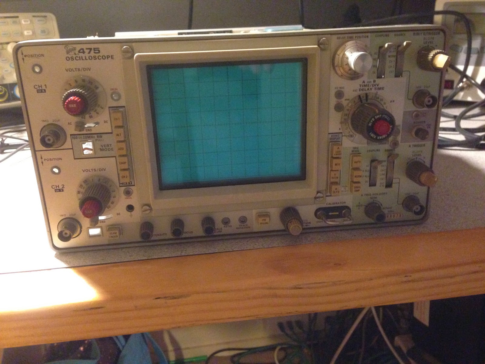
What is a Tektronix 475? Well it is a classic (1975ish) analogue oscilloscope. Pretty much the workhorse of its day and used for electronics development and testing. It's a beautiful and capable bit of gear that has 200MHz of bandwidth and some other cool delay and zoom features.

First of all you may be asking why I have one of these? Well I actually trained as a computer engineer so I did do a fair amount of electronics at university. As a teenager I messed around with radios and electronics as well as computers. Unfortunately I *hated* hardware at university!

I thought it was the the maths that put me off but now that I am getting back to it I think it was more that the teaching was atrocious. I was telling this to a friend of mine (Owen who is also a computer engineer from UNSW) and he was saying there was a 3rd year electronic subject where in the final exam he was able to answer maybe one and a half questions out of five and got a distinction! Essentially they scaled everybody just to get sufficient passes! I actually took all the software options from 3rd year up because I found the analogue electronics subjects so awful. I did try one subject in 3rd year but then quickly changed back. I too remembers some shockers in 2nd year where nobody I knew passed the exam but somehow we passed the course.

Well I've been playing around with this stuff again. I have been re-teaching myself circuit theory including AC analysis and basic building block circuits with transistors, op amps and FETs. I've been reading lots, watching a few youtube channels (like this guy http://www.eevblog.com/ Dave is awesome!) and reading a few forums.

I now have a cheapo Siglent SDS1062C scope, a SDG1020 signal generator and a (not so cheap) Agilent U1242B meter. I chose to get a decent meter as I think it is worth it for safety. I have a cheapo (unfortunately single channel) 30V/3A linear bench supply also and a collection of electronic components (many are quite ancient) plus a few breadboards.

Tek 475

I bought the scope as it was (a) broken (and I wanted to fix it!) and was (b) local so I didn't have to pay postage and (c) cheap! It turns on, the lights etc all seem to work and behave as you would expect but no screen display. The knobs etc are all in great condition and the front panel is clean and free of scratches and general cruft that you would expect on a 40 year old instrument.


Amusingly it comes with an extensive service manual (inch thick paper!). It's available online also from Tektronix (http://www.tek.com/manual/475). I also found another version that was edited by the US DOD and included more extensive troubleshooting guide and included waveforms.

I located the EHT circuit in the manual and looked for what components or areas could be faulty. I opened the thing up and looked around to see if there was anything obvious that might have died. At this point I was poking around with a meter while the unit was unplugged as (frankly) a couple of kV of energy scares the shit out of me!


The thing is a bit of a mechanical work of art too. There are a load of pots attached to long fibreglass extension shafts that connect them to the knobs on the front panel (presumably to minimise cable runs). Mostly the boards interconnect either using these long runs of right-angle pin connectors or using short coax connections but there are a few spots where they have just soldered something on. Also there are a load of components that look like afterthoughts tacked onto the circuit - like the capacitors around the high voltage area etc.

I had no luck finding anything obvious. I opened up the shields on the EHT area and I noted there were two neons in the high-voltage areas so I decided I would power the thing up and see if they glow. They didn't and in fact the -2450V testpoint was at.. well zero. Hmm.

PSU

I noticed that the high voltage depends on the 15V unregulated line, the -8v supply and the 110V supply. There are well marked test points for all the voltage rails so I powered on and checked each. The -8V was at +800mV! And the -15V was at -23V. The 15V unregulated output looked Ok as did the fuse that protects the power going into the primary side of the high voltage transformer.

Looking at the circuit, the chip containing the op amps that are the error amp for the -8V and -15V uses the -8V line as VSS. Ok so -8V is causing -15V to be wrong too. There is a diode (CR1468) clamping -8V from going positive so the 800mV is probably the diode drop.


Then I noticed the bridge rectifier for the 5V supply had been replaced. It was sitting above the board and had been soldered onto the top side instead of being soldered on the solder side. Also there was a link going to the filter cap for the 5V.


Turns out the filter caps have 3 legs as their can is grounded. Someone had replaced the 5V one (it was blue instead of silver) and they had bridged the centre leg spot with a link.

My best guess was the rectifier on the -8v line had gone tits-up. The main board is a nightmare to remove. 

I bought a replacement bridge from Jaycar and attacked the regulator with a pair of side-cutters (destroying it), When I got down to its legs I carefully desoldered them from the board and soldered in the new bridge slightly off the board. I turned the unit back and what do you know! -8 and -15 now work! But still no EHT :( Not that easy... Oh well.

I did a few more tests and 50V was more like 54V. The other supplies were all similarly off. The other supplies all you the 50V line as a reference voltage. I found a pot for adjusting the 50V supply and twiddled it until I got pretty close to bang on with the 4.5 digit meter (correct tongue angle was used).

The -8V is still a bit off (-8.3V) but the others are pretty close. I still haven't figured this out.

High Voltage Oscillator

The CRT circuit has an oscillator based on a transistor that switches the current through the primary side of a transformer. There is a feedback coil attached to the base of the transistor which switches the transistor off again. This change in current on the primary then induces a voltage in the feedback coil turning the transistor on again and so the cycle continues.

So my first suspicion was the transistor (of course) Q1318. Nothing else around there looked like it was having issues. The transistor was hard to find but it turns out it lives on a bit of metal down at the back underneath the main board and behind the vertical pre-amp board. The transistor looked ok on the multimeter (looked like two healthy diode junctions) but I read you can replace it with a bog standard 2N3055 so that's what I did! It was tricky to remove as I had to unscrew the preamp board and the corner of the main board and sort of bend them slightly to easy the box out. I put it all back together but no change.

While fiddling with it I noticed the graticule illumination was a bit dim. I checked the voltages and the +15V rail was in the toilet (8V). Damn. I checked a bunch of things, even disconnected the transistor but no luck. In the end I figured out I had squashed a ribbon cable when screwing the vertical board back down. I unscrewed it, pulled the ribbon out and then the short went away. In the mean while, while troubleshooting the problem I put a scope probe on one of the transistors in the 15V regulator circuit but I accidentally touched the earth ring on the probe tip to the metal transistor can. I got a small spark and the voltage *really* went off then. Luckily most of the transistors are socketed so I replaced it with a boring old BC557 and sure enough this worked.

Anyway - back to the *actual* problem! When I looked at the Q1318 collector test point on the scope, the it looked like the oscillation was just too small. It wasn't sinusoidal, the deflection was less than 2V and the frequency was only 30kHz instead of the 50kHz the service manual specifies. The average voltage was around 21V as expected (around the same as the unregulated 15V supply) but it just didn't look right. The only thing I had to go on was a very grainy photo of the waveform in the DOD service manual.

A bit stuck at this point, I talked to a friend about this and he offered to help me work on this. Graeme worked as an electronics tech for a long time and was excellent at breaking down the circuit to troubleshoot potential problems. The high voltage circuit includes regulation and will sample the -2450V output (via an impressive 24.5M Ohm ceramic film resistor) and adjust the oscillator accordingly. If the voltage is too high or low it alters the bias on the feedback coil of the transformer to suppress or enhance the oscillator. We suspected this was going wrong and clamping the oscillation down. 

The trouble was it all looked Ok. For a good while we couldn't figure out why the voltage swing on the oscillator wasn't bigger. We even tried temporarily adding more drive to the base to increase the current flow. This made the transistor warmer but the voltage swing was about the same.

Then Graeme figured out that if the transformer was effectively a dead-short then the voltage swing would be minimal


The high voltage output is fed to an EHT multiplier to generate the 15kV at the anode of the scope. I read somewhere that if the multiplier goes bad (and they do) that it will load up the secondary and the -2450V won't come up. The way to test this is to disconnect the EHT multiplier from the high voltage transformer. The next trick was finding it! Graeme guessed it was in this can below the main board. It looked like you could get to it but you have to remove the vertical pre-amp board. This had a couple of knobs, half a dozen or more coax connectors, two or three ribbons and the delay line. Annoyingly it was also soldered to resistors inside the front-end attenuators (bit probes plug into) and there was a cap soldered between the main board and the pre-amp board.

This thing also had these funky mechanical switches built right into the board. You can see the what look like tiny gold forks toward the top of the picture below. These all move when you fiddle with the bandwidth limit button. Note also the round black chips towards the bottom middle with square footprint? These are a custom ASIC! From the 1970s! That would have cost a bomb! Also the entire board is gold plated. It is a thing of beauty to be sure


Anyway we decided we didn't have the tools to pull this out and gave up for the day.

The manual listed the knobs as having a #4-40 1/8" set screw. Turns out this #4 is an American screw size, 40 means 40 turns per inch thread and 1/8" is the length in inches. #4 apparently has a hex slot size of 0.050" which is near enough to 1.3mm. I found a set of screw driver bits at Jaycar that had one of these and was able to undo all the set screws. I disconnected all the coax and desoldered what I needed to and removed the board from the scope. I removed the can around the high voltage transformer (bottom left below) and found that true to Graeme's intuition, the EHT multiplier was in there too.


EHT Multiplier is the black box on the left of the image below. Both this and the transformer were inside the can in the photo above.
I figured out which winding was which on the high voltage transformer and none appeared to be open. I decided to disconnect the EHT multiplier from the high voltage transformer to see if this was the problem (more desoldering).

I powered it on (with the veritcal board out of the scope) and it hummed a bit but nothing happened - no neons. I turned it off attached my DMM alligator to earth with the intention to check the voltage on the -2450 test point. I powered it on and as I brought my probe close it arced! So now -2450 appears to work! I turned it off, attached a scope probe to the collector of Q1318 to see what the oscillator looked like now and here it is! A beautiful sin wave with 30V amplitude!


Interestingly I got a bit of glow on the screen too which indicates the tube is essentially Ok. More good news!

So now I know what to replace but where do I get one? Some people make their own EHT multipliers as they are pretty simple - 3 voltage doublers back to back really. The trick is getting the right diodes/capacitors and then you have to pot the thing in epoxy else it will arc over.

Otherwise you essentially have to go on a transplant list and wait for another scope to die.

There is a company called QService that supplies parts for old (and even ancient) Tek scopes. They had no EHT multipliers in stock. I found a guy on ebay in Canada that sold some 475 parts and emailed him to see if he had this part. Turned out he did so I bought it off him.

That was a while ago however and I am still waiting for the part to make it via snail mail.

It's been a load of fun so far! I'm sure this won't be the last issue!

The story continues when I get the multiplier in the post!

Tuesday, 18 February 2014

Elevating just one part of an application

Elevation

In Windows Vista and up, even if you have administrator rights, applications you run can't perform actions that REQUIRE administrator rights unless the user is prompted with a UAC. The documentation refers to this as a 'split user access token' where the one you run with normally has restricted privileges but when you go to do something that needs administrator access it uses the full access token (after warning you).

I had to implement code in an MFC application for making changes to the registry that required administrator access. Our customers said they didn't want to run as an administrative user just to run the application (which is fair enough) so we modified the application to only require administrative rights when the GUI for editing the HKLM registry was invoked.

How it Works

Essentially you can invoke an out-of-process COM object and request that the object run with elevated rights. The COM object then displays a dialog for the user to edit the settings.

In my case most of the GUI to be displayed already existed so all I needed to do was to provide a wrapper for it.

In the dialog where the elevated GUI is invoked, the button that invokes the elevated dialog is initialized to display the familiar shield icon (so users know it requires elevation). 

Also, we need to be able to still run on older OSes. If we are not on Vista (or later) we check if the user has access to the HKLM registry. If we are on an older OS and the user doesn't have access we just disable the button.

if ( m_isVista )
{
    Button_SetElevationRequiredState(
        m_editWithElevationButton.m_hWnd,TRUE);
}
else
{
    if ( ! canWriteHKLM() )
    {
        m_editWithElevationButton.EnableWindow(false);
    }
}

MFC and ATL

Making an MFC COM object proved to be too hard. The easiest route was to make an ATL DLL that supported MFC. There is an article here that explains how to do this but in essence what was required was to create a WinApp instance and to register the MFC extension DLLs where the GUI was loaded from.

Invoking with Privilege

For a COM object to be elevated it must satisfy a number of requirements (documented in this link MSDN). The elevated GUI Wrapper COM component must:
  • Have a LocalizedString value under the HKEY_LOCAL_MACHINE/Software/CLSID/{XXX} registration point that refers to a resource where the display name of the components is stored.
  • Have an Elevation key with a DWORD Enabled=1 below the registration point.
  • Optionally have a IconReference under the Elevation key referring to an icon resource within a DLL that is to be displayed.
  • If Over-The-Shoulder elevation is required (where the administrator logs on with their credentials over the shoulder of the non-administrator user) then the DACL on the registry keys for the COM object must be updated (see MSDN reference above).
Also the COM object must run as an Out-of-process server (or local server). To enable this the DllSurrogate registry value must be present below both the COM registration location and below the registration location of the associated 'app ID'.

In addition it is desirable for the COM object to be signed. Otherwise the user will be warned that the application is not signed when they are prompted to elevate.

The registry requirements can be achieved by editing the .RGS file resource as follows which results in the registry being updated when the COM object is registered either by regsvr32 or by the installer:

HKCR
{
    NoRemove AppID
    {
        '%APPID%' = s 'ElevatedGUIWrapper'
        {
            val DllSurrogate = s ''
        }
         
        'ElevatedGUIWrapper.DLL'
        {
            val AppID = s '%APPID%'
        }
    }
}


And then the following registry is required for the COM class:

HKCR
{
    ElevatedGUIWrapper.ElevatedEditor.1 = s 'ElevatedEditor Class'
    {
        CLSID = s '{...}'
    }

    ElevatedGUIWrapper.ElevatedEditor = s 'ElevatedEditor Class'
    {
        CLSID = s '{...}'
        CurVer = s 'ElevatedGUIWrapper.ElevatedEditor.1'
    }

    NoRemove CLSID
    {
        ForceRemove {...} = s 'ElevatedEditor Class'
        {
            val AppID = s '%APPID%'
            val LocalizedString = s '@%MODULE%,-101'
            ProgID = s 'ElevatedWrapper.ElevatedEditor.1'
            VersionIndependentProgID = s 'ElevatedGUIWrapper.ElevatedEditor'
            ForceRemove 'Programmable'
            InprocServer32 = s '%MODULE%'
            {
                val ThreadingModel = s 'Apartment'
            }

            'TypeLib' = s '{...}'
            Elevation
            {
                val Enabled = d 1
            }
        }
    }
}

To invoke the COM object with administrator rights you need to do something like this:

HRESULT CoCreateInstanceAsAdmin(HWND hwnd, REFCLSID rclsid, REFIID riid, __out void ** ppv)
{
    BIND_OPTS3 bo;
    WCHAR  wszCLSID[50];
    WCHAR  wszMonikerName[300];
 
    StringFromGUID2(rclsid, wszCLSID, sizeof(wszCLSID)/sizeof(wszCLSID[0]));
    HRESULT hr = StringCchPrintf(wszMonikerName, sizeof(wszMonikerName)/sizeof(wszMonikerName[0]), L"Elevation:Administrator!new:%s", wszCLSID);
    if (FAILED(hr))
        return hr;
    memset(&bo, 0, sizeof(bo));
    bo.cbStruct = sizeof(bo);
    bo.hwnd = hwnd;
    bo.dwClassContext  = CLSCTX_LOCAL_SERVER;
    return CoGetObject(wszMonikerName, &bo, riid, ppv);
}

When elevating there are two scenarios depending on the rights of the logged on user. If the user is an administrator then elevating simply enables their administrative rights. If the logged on user is not an administrator then windows asks the user to logon using an administrator credential. In the second case the idea is the user asks an administrator to log on for them and watches over their shoulder while they perform the required action. This is the 'over-the-shoulder' or OTS scenario.

To enable OTS elevation the COM object's launch and activation permissions must be configured to permit a non-administrative user to launch/activate the COM object. The MSDN guide on creating elevated COM objects suggests the "LaunchPermission" registry value below the App registration should be set to a security descriptor built from the SDDL below:

O:BAG:BAD:(A;;0xb;;;WD)S:(ML;;NX;;;LW)

The 'AccessPermission" value should be set to the following SDDL:

O:BAG:BAD:(A;;0x3;;;IU)(A;;0x3;;;SY)

Making it look Modal

If the application simply instantiated the COM object and called the method to display the dialog, then while the method was blocked waiting for the COM object the application would be starved of updates and would not re-paint itself correctly. Ultimately the application would be treated by windows as a non-responsive and (after a few errors are displayed) would get terminated.

We want the elevated dialog to appear like a normal modal dialog to the user so we do a number of things:
  1. The implementation invokes a thread that instantiates the COM object (either elevated or just as a regular object) and calls the method to invoke the elevated GUI. This method will block the thread until the editor has completed.
  2. The Window handle of the main application window is passed to the COM object. The COM object opens the dialog modal to this parent window which has the effect of disabling parent window and implementing the usual blink behaviour if the user tries to interact with the parent window.
  3. After invoking the thread the process uses a peek message loop to process any windows message and wait for the thread to terminate. See code snippet below.
  4. If an exception is thrown as a result of an error interacting with the COM object, the thread saves the error as a member of the class and when the thread completes the main thread of execution throws the saved exception to the caller.
The peek message loop using MsgWaitForMultipleObjects looks like this (see below). This has the effect of processing any messages that occur in the parent application while otherwise blocking the application until the thread exits. The thread waits for the COM object and exits when the dialog is dismissed.

while(MsgWaitForMultipleObjects(1, &m_hThread, FALSE, INFINITE, QS_ALLINPUT) != WAIT_OBJECT_0 )
{
    AfxPumpMessage();
}