Showing posts with label Sweep Generator. Show all posts

Thursday, 10 August 2017

Rohde & Schwarz SWP.339.0010.02 Synchronizer PLL unlocked

Last time I fixed a problem in the sweep generator where the 600MHz IF was being disabled when it shouldn't. After that all the self-tests passed and the unit was working overall except that when using the Synchroniser with frequencies above about 980MHz it would lose lock.

Lock Loss

The loss of PLL lock would occur around 980MHz but is wasn't reliable. Sometimes the output would be stable up to 1GHz but then after the unit warmed up a bit it would revert back to the usual behaviour.

This is what the output look like on the spectrum analyzer when the PLL is locked and the frequency relatively is stable (in fact this snapshot isn't all that great - it got better later).


Then if you shift the frequency ever so slightly the output would loose it all together.

The Synchronizer PLLs

The synchronizer has two PLL loops used to lock the output frequency to the 10MHz reference.

In the block diagram below the 'fast' PLL is shown in green and the 'slow' PLL is red. The slow PLL locks a 87-122MHz VCO to the 10MHz reference. The fast PLL divides down the output using a set of frequency dividers


The way it all works is that there are a few paths depending on the frequency range.
  • Below 20MHz the output is generated by mixing the VCO output with the 100MHz reference signal generator off the converter board. In this case the output is not fed back through the PLLs.
  • Above 20MHz but below 70MHz the output frequency is band-pass filtered and fed to the PLLs
  • Above 70Mhz and below 700MHz the output signal is divided by 10 and then fed to the fast PLL and the 700Mhz fed to the fast PLL
  • Above 700MHz the output is mixed with a 1200MHz signal derived from the 600MHz IF generated on the IF board to down covert the frequency to 0..700Mhz. This is then divided by 10 to get 0..70MHz which is fed to the fast PLLs. The 700Mhz is again fed to the slow PLL
  • Above 1200MHz the output is mixed with an 1800MHz signal generated from the 600MHz IF and the 0..700Mhz fed to the PLLs as above.
When the output is below 20MHz the slow PLL locks the VCO to the 10MHz signal.  There is a phase comparator that compares the VCO output with a 10kHz and a 1kHz signal generated from  the 10MHz reference. Because the 100MHz this is later mixed with is also locked to the 10MHz reference then this is all that is required.

When the output is above 20MHz the slow PLL takes the 0..70MHz signal derived from one of the paths listed above is divided by a factor K and compared with the 1kHz and 10kHz reference derived signals and used to control the VCO.  The VCO is then divided by 64 to generate a signal between 1.5Mhz and 1.9Mhz that is fed to another phase comparator and then used to control the output frequency.

The fast PLL does its own division of the 0..70Mhz signal (divides by M and then by N) to generate a frequency around 1.5MHz to 1.9MHz which gets fed to the phase comparator described above. The fast PLL has extra logic for sweeping so it can lock just at the beginning of a sweep and can handle fast frequency transitions that the slow PLL can't.

Debugging PLLs

So I was dreading this problem because of the  PLL loops. The problem is that if the loop is out of lock then all of the loop is out of lock and it's hard to tell where in the loop the fault lies. In this case it is even  worse because there are two PLL loops.

Initially I mistakenly thought I could check the slow PLL on its own. I thought it was totally derived from the reference and so should remain in lock regardless. That isn't the case as it does depend on the output. Therefore if the output is unlocked so is the slow PLL and the VCO.

With a brief warm up I could get the unit so it would be in lock and then if I shifted the frequency just a bit it would lose lock. This made debugging easier as I could compare the 'working' with the 'unlocked' states quite easily.

So I started with the slow PLL and began with the VCO. I found that when the loop is locked the VCO frequency was stable but when it lost lock the frequency would jitter. Also I found that the frequency would go to 132MHz which is outside the specified range. Stepping back through the VCO inputs I found that the control voltage was hitting the limits (going to zero) when it lost lock. I walked back further and found the two phase comparison signals (PHKOM11 and PHKOM12) coming from the digital board were hitting the rail (15V) when the PLL lost lock.

Digital Section

Debugging the digital section wasn't much fun. It has two SMB connectors through to the motherboard and I didn't have any SMB patch leads - I have SMC and SMA (both of which are used in this instrument) but not SMB. This meant I can't run the board on risers as the signals on the coaxial connectors are required to debug the PLL loop. I found I could connect to the test points with a wire and then stuff the board back in the unit.

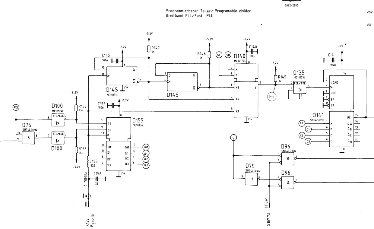
First I looked at the test-points around the dividers (see below). To be honest I don't really understand this circuit. It's a messy mix of ECL and TTL with lots of TTL to ECL conversion going on. There are ECL D type flip-flops feeding ECL counters that adjust to either count by 10 or 11(??).


The core of this is this two chip set that implements a pre-scale and phase comparator. This is the HEF4751VD and HEF4750VD. The pre-scaler has more capability than what is used here but the circuit seems to be controlling these two 4 bit registers that are used to subtract from the count (to adjust the divide ratio). There is a feedback path that clocks out signals that then adjust the counters feeding into the pre-scaler.

Ok so I got a bit lost here but I could see the 10kHz and 1kHz signals at P9 and P10. When the loop lost lock the frequency of these would drop just a little. The phase comparator output would alter also and that matched what I was seeing on the analog board.

So the question is why is this happening? I thought about maybe the counters are not being setup correctly so the division ration is wrong, I traced signals in to check that they aren't being lost (and they weren't). It seemed to be working apart from the fact that it lost lock.

It was about here that I realized that the input is a 700Mhz signal and not the VCO. I also realized that if either PLL was wrong they would both lose lock.

I start looking at the fast PLL - I looked at the frequency of the P11 signal. This signal has already been divided by 10 on the analog board and is divided by another 1,2 or 4 depending on how many of the D flip-flops are enabled by the multiplexer (D140).
You can figure out the division easily from the table provided in the service manual below. You take the output frequency, work out the down converted freqency by subtracting it from either 1200 or 1800 (or don't subtract if it is less than 700Mhz) and you look up this frequency in table. Then you divide the frequency by M and that should be the frequency at P11.


Again I found this matched exactly - or at least it did when the PLL was locked. When it fell out of lock the frequency would wander off (lower).

New Piece of Test Gear

Up to this point my only way of checking the output frequency above 300MHz was with my spectrum analyzer and I wasn't confident this was correct. A while ago I ordered a pre-scaler for my frequency counter from this polish eBay seller and it finally turned up. The quality of the board and the wiring etc was excellent. I installed this in my 53131A and did some tests. It happily counts -30dBm signals up at 2.5GHz.

Tuning the YIG

One thought I had was that because the YIG output was very out of tune that this could effect the synchronizer PLL's ability to lock. Up to this point I could adjust it as I couldn't measure the output with any accuracy. I followed the procedure to adjust the low end (10MHz) and then the high end (2.5GHz) using my new pre-scaler.

Then I tried the synchronizer again - and it locked at 2.5GHz!

The problem was simply the YIG being too far out.

That was too easy. Well at least I learned a few things.

Final Cleanup

So here it is in my bench (gee it's getting crowded!).


I even took the time to polish up the BNCs with a bit of aluminium polish and a Dremel tool. They look good!


Friday, 28 July 2017

Rohde & Schwarz SWP.339.0010.02 - Synchroniser

So in my last post I began debugging a fault with where the output of this sweep generator was stuck at one frequency because the 600MHz IF was disabled. This fault went away so I started debugging the next issue. I managed to make some progress before the 600MHz fault returned.

Playing with the Synchroniser

My main application for this unit as as a sythensizer and the sweep functionality isn't overly useful as I have the spectrum analyser with tracking generator. So now that the unit is generating an output I wanted to play with this.

Without the synchroniser enabled the output is miles off. 10MHz comes out as 7, 100MHz as 104MHz, 1GHz is nearly 15MHz off. My understanding is this is pretty normal as the YIG is hard to steer accurately.

With the synchroniser on the output is really close according my frequency counter. My counter can only count up to around 300MHz but at this frequency it is less than 20Hz off. No idea which of the two is more accurate at this point.

I noticed an anomaly however in that if I choose a frequency less than 20MHz the output was spot on. If I chose a frequency above this (like 20.001MHz for example) the output jumps off to 54MHz or so and wanders around. After experimenting a little I figured out that above 70MHz it comes back together again. So what is special about this frequency range?

Understanding the Synchroniser

The block diagram below shows the major functional components of the synchroniser. The bit highlighted in green is what I figured had to be in the signal path when it was going wrong.

The basic plan here is to take the output signal, divide it down enough that you can lock it to the reference frequency and then generate an phase error signal that can be fed back to the sweep board to adjust the frequency of the output. A big PLL in other words.

It's not that simple though as the frequency range is broad and because the unit can sweep rapidly across a range while maintaining lock on the reference. For now I'll neglect a lot of this detail and just focus on what was going wrong.

If the frequency is between zero and 20MHz the 97-122MHz VCO is locked with the reference and mixed with the 100MHz coming from the converter board to generate the output signal (doesn't use the YIG at all).

Over 20MHz it starts to look at the output signal and processes that down to something it can compare with the reference. There are three ways it can do this
  • Take the output signal, filter it to cut-off anything above 70MHz and use this directly.
  • Mix the output signal with a 1.2GHz signal produced by multiplying the 600MHz generated on the converter board. Then take the 0..700MHz output and divide this by 10 to give a 0..70MHz signal and process that
  • Mix the output signal with a 1.8GHz signal produced as above and divided as above.
The path it chooses depends on the frequency range it is generating an output in. The first bit that is confusing is that the schematic shows the first of these paths as producing 0.1..70MHz where as in the 0...20MHz range a different path is used so this isn't true.

So in my case it had to be something in this 0.. 70MHz filter or the switch as everything else works in other bands.

Synchroniser RF Board

The synchorniser RF board is another fine work of RF voodoo. The multipliers and distributed element filters look pretty interesting although I have only the vaguest clue how they work.


Thankfully none of that mattered as I was looking at a relatively low-frequency path through this board. Here is a block diagram of just the RF section with the areas I was interested in high-lighted.

Now it did take some trial and error as well as head-scratching to narrow the schematics down to this. The other annoying thing is that two of the connectors on the RF board are the SMCs similar to the converter board but two are SMB connectors. I have patch leads for the SMCs but not SMBs so I also wasn't sure if what I was seeing was correct because things were disconnected.

As it turned out this wasn't a problem as the SMBs were generally outputs and even though the system might not have been working, the board I was looking at was running as it would if it were plugged in (and not up on riser boards).

The schematic below shows the low pass filter (shown as 100MHz but the other block diagram showed this as 70MHz).


The three amplifiers at the top marked D70 plus their associated components carried the signal in this 20..70MHz range. They use this ECL NOR gate chip (D90) as a sort of switch to control the signal path. One of the inputs is a control line and the other carries the RF signal.

Because this is ECL the logic levels are between -2.5V and ground which looks a bit odd at first but you get used to it.

At the top right are two gates (near R95 and R92) that feed into another one below (near R94). I was looking at the signals on the pins of D90 and it seemed like one of these gates wasn't switching it through. Eventually I figured out that pin 14, 7 and 4 should all have the same signal but they didn't.

I pulled the board out and checked continuity and sure enough there was no connection. Thankfully the chip was socketed so I pulled it out and checked continuity again.

It turned out that pins 14 and 3 are directly connected by a track and another track from 7 meets them at a via. The via was basically loose enough that it made intermittent contact. I soldered a jumper wire between the pins, re-tested and it basically worked.


Still more Problems

So at this point the unit is looking pretty good - the 600MHz problem seems to have gone and now the synchroniser problem is solved. All the self-tests pass and I can generate relatively accurate signals.

I did notice that if I used my spectrum analyzer to look at the output, as the frequency goes above 1GHz the accuracy gets steadily worse. At 1GHz it is less than 1MHz off but by 2GHz it is nearly 20MHz.

While looking at this and pondering if this is a fault or just a limitation of the device my 600MHz fault (self-test code 22 1C 00) came back again.

So I suppose I better look at that next!


Thursday, 20 July 2017

Rohde & Schwarz SWP.339.0010.02

I have a new thing to fix! It's a sweep generator that can produce signals from 400kHz to 2.5GHz and -130dbM to +13dbM. It's very big, heavy, old and broken!

So What's it Do?

This thing is a specialized  sweep generator that can quickly sweep across a frequency range. In addition to the RF output the generator produces a voltage which is proportional to the output frequency that you can use as the X input to your oscilloscope in X-Y mode. This allows you to produce frequency vs amplitude response curves for filters, amplifiers etc using the generator and a scope. It's pretty much the tracking generator part of a modern spectrum analyser. R&S sell other bits of gear that work with this one to provide network analysis and other features.

The thing uses a YIG (Yttrium , Indium, Gallium) tuned oscillator to produce the output frequency since YIG oscillators can be rapidly tuned over a broad frequency band. Unfortunately they are not frequency accurate without additional circuitry. R&S sell a 'synchroniser' option which is pretty much a fancy PLL circuit that allows you to lock the output to a crystal oscillator to get frequency accuracy. My unit has this option fitted.

In addition R&S sold a marker option and while my unit is fitted with this option I've not really touched it. I think it generates pulses so you can create tick-marks on your scope at specific frequencies.

Another option is the mechanical step attenuator that allows the unit to generate a broad range of output levels. Mine is also fitted with one of these which is pretty nice and it makes an amusing array of clunks as you wind the knob to adjust the output level.

Physically the thing is massive - weighs nearly 20kgs and is packed with boards.  It's got a huge linear supply with a shielded torroidal transformer and the back panel (which acts as a heatsink) gets quite hot when operating.


It has a big bright LED user interface and lovely clunky keyboard interface. The adjustment knob feels lovely to use as it is really solid and has a gentle cogging that feels a bit like a turning a very soft stepper motor. The knob will easily whizz if you flick it and it comes to a gentle stop.

I found the user interface a bit confusing at first - still do really. You have three numerical displays which are the start, marker and stop frequencies. The keys have second functions that are activated by a second function button marked with a red circle. To get a constant frequency output you have to use the second function button for example. There is an LED marked RF off and a button. By default the output is on unless you hit RF-off and then the light comes on. I feel is exactly the opposite of what I would expect.

I had no idea what 'synchronizer' meant and assumed it was something to do with interfacing it to a network analyzer. 'Synthesizer' would have made more sense as that is what this option does - makes the unit a synthesizer.


Condition

Overall the unit is in pretty good physical condition for its age (I think it is an early 80s device). There are little bits of corrosion on some boards/connectors which is concerning but probably Ok. It's got minimal amounts of the usual cal sticker residue and the paint on the rear and top/bottom panels is in reasonable state.

The first time I turned it on it was apparent the switch is broken as I had to hold it in to keep the unit on. This might have been transit damage.

In the ebay listing the seller noted it displayed error 10 A when the self-test runs. Before I bought the unit I looked this up and found it indicates the settings battery is dead. Could I be that lucky? When I opened it up I found the battery is in fact a pair of AA alkaline batteries and they had not been replaced in such a long time that they have eaten their battery holder. The battery doesn't matter too much as it is only used to store pre-sets. The unit operates fine without it.


I connected the unit up to my spectrum analyzer to look at the RF output but unfortunately it didn't look like it was working. The output was constantly around 38Mhz regardless of the settings. Doing this test  required some creative operation  as I needed to keep my finger on the power button to keep the unit on!

Power Button

First things first - the power button had to be sorted out as I couldn't do anything sensible with  the sweep generator while holding the power button in. The power button is at the back of the unit near the mains input and is connected via a long shaft to a power button in the front panel.

Knowing the likely outcome I removed and disassembled the power button anyway. The main shaft that is pushed by the rod has a hole for a pin that implements the push-on/push-off mechanism and this hole had been wallored out from many years of use.


I started looking for a replacement but the switch was made by Petrick and they went out of business long ago. The other problem was I found it pretty hard to find the right keywords to specify a push-on/push-off  plunger type switch with a square rod. It also needs to handle quite a few amps at 240V.

Even if I could repair the existing plunger I don't think the one I had was going back together any time soon :)


In the end I found a replacement switch that is a KDC-A04 and they are pretty common in cheap Asian electronics. They have the right number of poles, roughly the right throw and the right size plunger. The one problem was the size of the tabs used to screw it down where different. I found I could get enough purchase under the screw on the opposite side (even though the screw didn't go through the hole) for the switch to be pretty secure. I did have to slightly shorten the plunger but it worked just fine.


No Output

I got a partial copy of the user and service manual before I bought the unit from the R&S yahoo forum. Unfortunately these included the first 20 pages or so and the manuals are a mixture of English and German. I realized quickly that I needed more and began looking around for the rest of the service manual. The most economical option was to buy the two service manuals for 20Euro each from an online vendor. The paper manuals were nearly triple that! That's actually more than I paid for the generator!

Once I got the service manuals and started reading the more I started to figure out the self-test mechanism. The generator has an extensive set of self-test lines and can localise faults to some extent by itself. The first error displayed was the battery failure but you can hit the clear key to get past this and see other errors.

The first error was a failure of the 600MHz IF. This explains the lack of output. The other errors were likely a result of this first error.

How it Works

So the YIG oscillator generates frequencies from 4.2GHz to 6.7GHz. The output is generated by mixing this with an internally generated 4.2GHz signal generated from the 10MHz reference clock. The YIG is then tuned by sweeping the control voltage to vary the output frequency. This is all achieved within one of the large, RF shielded boards called the converter board. The block diagram below illustrates how this works:

The process is broken into:

  • A 100MHz VCO that is locked to the 10MHz crystal reference using a PLL
  • A frequency multipler to generate the 600MHz
  • A helical tuner to filter the 600MHz
  • An amplifier for the 600MHz signal (as it is used elsewhere in the unit)
  • A multiplier to generate the 4.2GHz signal from 600MHz
  • A filter for the 4.2GHz 
  • A mixer to combine the 4.2GHz with the YIG output

Debugging  down Rabbit holes

In my case the 600MHz was missing so I disassembled the converter and started tracing the signal through. The converter internally was quite interesting as it has a number of distributed element filters and a lot of hand construction.

Here you can see the 4.2GHz filter composed of the series of diagonal sections followed by a filter and at the top left is the mixer

The section at the top right is the 100MHz VCO and the bottom section to the right of the coils is the multiplier that generates the 600MHz from 100MHz. The  area at the top is the phase detector and frequency dividers etc that form the PLL.


The next trick was how to debug this. The case is quite closely packed so there is no hope of sneaking a scope probe down between the boards when they are in place. I found that R&S kindly supply a set of riser boards inside the unit that you can use to operate modules while they are up above the rest of the unit. The problem then is all the coaxial connectors that go in/out of the module which are all SMC (not SMA or anything common). I found a set of short SMC male to female patch leads that were perfect for the job on ebay. They look like this and allow me to connect the board to the coax cables inside the case


Running the converter board up on the extender boards with the patch cables plumbed in, I used a scope probe attached to my spectrum analyzer to measure what was going on. I found that the frequencies were way off. The 10MHz signal from the reference looked fine but...


The 100MHz was off a bit so instead it was more like 98MHz.


This got worse when it was multiplied so instead of 600MHz it was more like 589.


The output of the PLL PI filter was at the limits of the voltage range so clearly it was trying to force the VCO to 100MHz but couldn't. Because the 600MHz was so far off the filter was knocking it down a lot before it got to the next stage. Could this be the problem?

Apparently Not

I then looked at the service manual again. Apparently you can't operate the converter with the top cover removed as it effects the VCO (face-palm). Re-attaching the top cover and re-testing I found that the 100MHz signal was just fine as was the 600MHz coming into the following amplifier. What came out was pretty much nothing however. So in the schematic below the signal coming out of the 600MHz filter was fine but nothing was coming out of V82. What's more the test voltage at MP-10 and MP11 were off.


I also checked the circuit feeding V83 which is used to disable the 600MHz output (for example when re-tracing during a frequency sweep) but this appeared Ok.

So I ordered some BFR35 transistors and replaced V82 (feeling pretty sure this was it). I tested this again but no luck.

Intermittent

One really annoying thing about this unit is that the faults are very intermittent. I found that by fiddling with the controls it would randomly come good and start producing output. I figured out that the control that seemed to fix it was the one that disabled the output while the sweep re-traced.

I started monitoring the signal that disables HF output and looking at V249. See below.

On one of the occasions that this worked I realized that the 'HF off TTL' signal was effectively active-low. That is when the signal is high the HF is disabled and when it is low it is enabled. So actually when the signal coming in on pin C15 of the motherboard connector was high the output was disabled.

So actually the fault is elsewhere!

HF Enabled

The service manual is not much fun to read through. It's a huge file and so it is slow to scroll. The manual has been scanned as images so you can't search and it alternates the sections between English and German. Maybe this is because I don't have all  of the user manual but I couldn't find information anywhere that showed the location of each card. I had to effectively draw my own map by pulling each one out and comparing it with the drawings in the service manual.

Each schematic has the IDs of the connectors but then the cables have different designations and so it isn't always easy to figure out what signal is what and where it goes. The big block diagrams don't label the signals at all.

Now the HF off signal is referred to in other sections as HFSW1. There is also a HFSW and HFSW2 which are different! It turns out the HFSW1 signal is generated by the Sweep Control and Modulation amplifier.

So I connected up the sweep control and modulation board on the risers so I could start debugging this issue and half-way through I could no longer reproduce the fault. Before this I could re-start for the fault to return but now I can't in fact since then this fault has only come back a couple of times.

So I have to put this fault on the back-burner for now as I can't fix it if I can't reproduce it.


Next


So now it produces an but the frequency is pretty far off. The synchroniser does a good job of locking the frequency to the crystal but between 20.0MHz and 70.0MHz it totally looses it.

More debugging next time!