Saturday, 13 June 2015

Lab Power Supply - Current Sensing/Limiting (Testing)

In the last post I had the current sensing/limiting working however I had a problem with voltage overshoot when coming out of current limiting and I had problems with the pre-regulator. I think I have both of these nailed so here goes!

Current Limiting Overshoot

Last time I described a problem where the voltage would overshoot the set point when the circuit comes out of current limiting mode (see below). When the current returns below the current limit the voltage (blue trace) shoots back up but overshoots.


I experimented with various things. The main things were trying to use a diode to bypass the capacitor when the voltage drops. I also tried reducing the current flowing through the diodes (increased the pull-up resistor to 47K) and this also didn't have any effect. On the plus side it draws less current however so I will keep the change.

A bit stuck I turned to my trusty guide - the Agilent E3634 service manual and schematics. They take a different approach in that they sum the reference voltage and the inverted output voltage to drive the MOSFET. I noticed that there was a capacitor across the diode that joins the voltage error amplifier to the MOSFET gate. I wasn't exactly sure what this did but I tried it out. The circuit essentially now looks like this (I have added C8).


While it did not totally eliminate the over-shoot it reduced it to the point where it is negligible. I don't quite understand how this works - it is essentially capacitor coupling the voltage error amplifier with the gate driver.

When I tested this on the breadboard it looked like this (see below). The yellow trace show the current flow measured by the dummy load (1V/A) and the blue trace is the voltage output. The voltage shoots from zero up to 26V when the current drops. You can see a very slight upward deflection in the voltage and the top of the blue trace but otherwise it is pretty smooth. 


I did have a slight concern that this would effect the speed of the transient load response but here is the output voltage when the load switches from 0-2A and back again. It is still responding with 10uS in both directions:


This looks perfect to me! I am calling it fixed!

Pre-regulator

The other problem is that I found that if I set the pre-regulator to track the output voltage, when the supply goes into current limiting mode and then returned to constant voltage mode, the voltage would not return to the set voltage.

Having the pre-regulator track the output voltage is important. Otherwise if the pre-regulator sets the capacitor voltage based on the desired set voltage and you short the output terminals, the MOSFET would have to drop virtually the entire output power. I'd have to use a massive heatsink to support this. Setting the pre-regulator from the output voltage means that in current limit mode the MOSFET only has to drop a few volts.

To illustrate the problem, here is a trace showing the load current (yellow), the output voltage (blue) and the capacitor voltage (green). The output was set to 25V and limited to 500mA. The dummy load was set for 1A so you can see short spikes before the limiting takes over. The voltage never makes it back to 25V when the current drops as the pre-regulator voltage hovers around 19V.


Interestingly if you set the output voltage lower it works and although it isn't clear why.


It took me some time to replicate this behaviour in LTSPICE. I figured out that as I was simulating the transition from 3A to 1.5A and back again it was different to the breadboard test. I also had to increase the simulation time as the capacitor would take time to discharge.

I tried changing the Zener diode in the pre-regulator that determines how far above the set point it is aiming for but this didn't have much effect. I tried increasing the capacitor on the servo op-amp that controls the firing point but this made it worse. Then I experimented with smaller values and found that if I used a 470n capacitor it would work. The downside is that the charging of the bulk capacitor is less frequent (more sporadic) but it does work.

Here is another test with the 470n capacitor, with the dummy load set for 3A and the limit set to 500mA and the voltage set to 25V. The pre-regulator holds the voltage comfortably above the output and the circuit is functioning correctly.


When I vary the output voltage the pre-regulator moves accordingly which is fine.

Again I think I will call this fixed. I think the dissipation on the MOSFET is still significantly reduced by the pre-regulator. When I set the dummy load for a constant (and large current) and set the limit for a smaller output, the pre-regulator does a good job of maintaining a lower capacitor voltage so the output holds at the desired voltage and the current holds constant.

Tuesday, 9 June 2015

Lab Power Supply - Current Sensing/Limiting (Testing)

In this update I continue with the Lab Power supply project. The parts required for the current sensing/limiting circuit finally arrived and I test out my design. Yet again I got caught out with ground placement and I found a flaw in the circuit I planned to use. I find a couple of performance gotchas that aren't easy to fix and may require some compromises to be made.

Current Sense Resistor

I installed the 10m ohm current sense resistor in the negative supply rail close to the output. My plan was just to install the resistor and measure the voltage across it using a multimeter to see how it goes. I left the earth point for the grid supply and the control circuitry to be at the negative side of the sense resistor.

I tested the circuit to make sure it was still working and found it was oscillating wildly. I tried moving the earth point to be nearer to the output terminal (i.e. the other side of the sense resistor) but this didn't change anything.

After some head scratching it occurred to me that as the output voltage sensing is after the sense resistor and the output capacitor is before it, the sense resistor and output capacitor form a pole. I moved the output capacitor to be literally on the output terminals and the oscillation stopped. Crisis averted.

So then I started looking at the voltage across the sense resistor while loading the supply using the dummy load. The first problem is my shiny new scope only has 10x probes and the lowest settings is 10mV per division. So a 1A signal just makes it to 1 division and the scope would't trigger. I think the problem is that even if you clean up the signal with the high-resolution acquire mode, its too noisy for the triggering to work correctly. I measured the voltage using a multimeter and it seemed to match what I expected however (11mV which is within tolerance). More on measuring the sense resistor voltage below.

Current Sense Amplifier

I put together a 5V rail using a LM317 and cascaded it off the 40V rail I already have. I added the LT2050 current sense amplifier and configured it to amplify the current sense resistor voltage so that 1V at the output is 1A. This is actually a bit of a problem as the common mode range on this component is only up to 1.3V below the positive rail. I might have to run this off 6V to get the full current range.

The output was a bit disappointing in that there was a regular spike that seemed to correspond with the 100Hz bulk capacitor charge cycle. In the image below the yellow trace is one of the AC signals and the green is the output of the current sense amplifier with no load on the supply.


I thought that perhaps this could be noise induced in the wires. I am running a 15cm wire from a vero-board where all the high current circuits are back to a breadboard where the control circuits are setup. The voltages are pretty small so I thought it wouldn't take much to induce this amount of noise. 

I twisted the wires together to minimize inductance but this had no effect. I found an old USB cable that had a clip-on ferrite bead and decided to try using the bead as a sort of common-mode choke. I wrapped the wires through this a couple of times but this too didn't really help.


I tried fiddling with the bypassing and even tried adding capacitance but none of this changed anything. At this point I was trying to decide if the problem was in the amplifier or if there was some sort of noise current occurring.

I remember that my old Tektronix 475 can go down to 2mV/division when the probes are in x1 mode. I remembered an old EEVBlog video where Dave Jones measures the ripple and noise on the output of a supply using a pair of probes. The basic idea is to use two probes as a sort of differential probe.

Unfortunately my old scope has drifted a bit so it took a little bit of fiddling to get the traces right. I configured each probe for the minimum setting, grounded each channel in turn and adjusted the trace to be on the zero line. Then I inverted the second channel and added them together. Unfortunately if you ground both and hit add the trace moves. I figured out how much and compensated by adjust each trace half this amount. 

When I adjusted the scope correctly I got a relatively noise free measurement of the voltage over the sense resistor and I could see the same weird bump occurring in the voltage. This means the sense amplifier is working and the error is somewhere else!


I went back to LTSPICE and remembered that I hadn't updated it with the changes I made to the circuit after adding the sense resistor. I moved the output capacitor to be closer to the output terminals but this didn't change anything. I remembered I had moved the ground point to be near the output terminals (after the sense resistor) and I tried changing this in the simulation. Oddly this was the cause of the fault - I was able to reproduce the behaviour in spice. 


I moved the earth point back to the other side of the sense resistor and the problem went away. The voltage control/pre-regulator etc was still functioning correctly too.

Current Control Circuit

I constructed the current control circuit that I designed in the previous log entry:

For the current set point I just used a 5.6V Zener diode and a pot (so I could vary it).

I discovered there is an obvious hole in my plan - because of the diodes, the minimum that the current control circuit can pull the voltage down to is 0.6V. If the load is low impedance (in my case it was my dummy load) then often this isn't enough to get the current down to the desired level. This pretty much kills this approach.

I re-configured the circuit so that the driver transistor is diode-ored between the current and voltage control amplifier outputs (as I had before). When I simulated this I found that the voltage would overshoot  when it came out of current limiting and I wanted to see how bad this is in reality.

Here is a scope trace demonstrating the effect: The output voltage is set for 25V (roughly), the output current is set for around 600mA and the dummy load is configured to draw 1.3A in 1KHz pulses. The green trace is the current (1V == 1A), the blue trace is the output voltage. You can see the current shoot up to the dummy load maximum until the current control takes over and brings it back. This takes around 100us to get in range but 200us to be stable. When the current drops off the voltage control takes over and gets the output voltage back up to the set output. The problem is that it overshoots by approximately 3V. It's back under control in around 200us however. I'm not sure about the ringing in the current but it is likely that because the dummy load is actively trying to drive the current up to the set level that there is a tug-of-war happening between the control loops. I don't think this matters too much in any event.


Right now I am really not sure how to fix this. The reason this occurs is pretty clearly due to the slew rate of the op amps. As the current control amplifier output increases, the voltage control is decreasing  and the overshoot is where the current control overtakes the current control. If I make the voltage control slower then this will work but clearly I don't want to compromise on speed.

Pre-regulator

I presently have the pre-regulator set to the voltage set point but this has a big downside when the current control kicks in. The problem is that the pre-regulator is holding the capacitor at 30V even when the output drops to close to zero because the supply is in current limiting. The heat dissipation is quite considerable even with just 600mA being drawn.

I tried setting the pre-regulator off the output voltage and while this works quite well for a relatively static load, the pulsed load above completely stuffs this up. The problem is that often the pre-regulator is caught with its pants down when the load drops and the voltage control goes back up to the set level. The result is that the output voltage is quite unregulated when the load drops out.

Again, I am not sure what I can do about this as the voltage is swinging between the extremes. Either the output will be low or the transistor will dissipate a lot of heat. This will require some thought.


Wednesday, 20 May 2015

Lab Power Supply - Current sensing/limiting

I've made some progress on the current sensing and current limiting circuit design but I'm still not quite there yet. This turned out to be a lot harder than I thought. I split the design into the part that measures the current and the circuit that controls the voltage regulator to limit the output current (current error amplifier).

My goal was to be able to measure and limit the output current to an accuracy of 1mA across the whole current range (0-5A) and the whole voltage range (0-30V). I wanted the current limiting circuit to be as quick as the voltage regulator but I found this isn't possible.

Basics of Current Sensing.

The idea is that we want to be able to set a maximum output current so that should something go wrong in the circuit powered by the supply, the circuit won't be damaged to much. The first part of the problem is actually measuring the current flowing.

While I will try and explain the basics here, I suggest looking at Linear Technologies Application note 105 as I think they do a better job.

The current sensing circuit measures the current flowing out of the power supply by inserting a small resistor in the power supply circuit and then measuring the voltage across this resistor. The resistor can be connected either between the positive side and the load (high-side) or between the load and the negative negative size (low-side).

High-side sensing is harder to implement as the inputs are likely close to the power supply rail (more on this later). The problem with low-side sensing is that if there is another path to ground that doesn't go via your sense resistor, you won't see any of it. I don't think this is a problem for my power supply as even if you tied the negative terminal to ground (and then grounded the negative side of the load) it would still complete the circuit via the ground part of the supply.

Current Sense Resistor

Choosing a current sense resistor and the amplifier to measure the voltage is quite tricky as you need to trade off the cost of heat dissipation in the sense resistor with the accuracy.

Working with the worst case settings of 5A, if I choose a 1 ohm resistor as the sense resistor then each mA of current generates 1mV across the resistor (which is easy to measure). However this will dissipate  P = I^2 * R = 25W of power at full load. That's enough to require a heatsink and the increased temperature will cause the resistance value to vary (due to the resistors tempco). Also, this will drop 5V from the maximum voltage the power supply can deliver at full output.

On the other hand if I use a 1mOhm resistor then this will only burn 25mW and there is only 5mV drop. The problem then is that 1mA only generates 1uV on the resistor which is well below the offset voltage of many op amps. 

The solution is to use 10-50mOhms which is still only 250mW - 1.25W, and 50mV - 250mV drop. Then 1mA will measure between 10uV and 50uV which is still pretty small but much better.

Current Sense Amplifiers

There are a few different ways of implement the current sensing circuit. Apart from high-side vs low-side you also have the choice of using a dedicated current sense module or to build one from op amps. Also, some of the high-side options are powered from the circuit they are monitoring and some can be run off an independent supply, There are modules that support digital output but this is no good unless they also provide an analog output as I need this for the current limiting circuit. Some have a fixed gain (or a set of fixed gains) where others can be configured with resistors.

A couple of the critical parameters for me were the ability to sense the current when the voltage is close to zero, having 1mA resolution (so therefore 5uV-25uV offset voltage) and an input range (common mode range) of 0 - 30V.

So I started by looking at dedicated, high-side current sense amplifiers and went through the manufacturers.

  1. From TI I found the INA-225, INA-250A2 to be the only ones that came close. Both had offeset voltages in the vecinity of 100uV or more which would mean I need at least a 200mOhm sense resistor which equates to 1V drop and 5W of power lost. The bandwidth is pretty bad too at between 5kHz and 250kHz.
  2. From Linear Technology I found the LT-1999 and LT-6105 that support he common mode voltage range I am after but both have silly offset voltages (300uV and 1.5mV). 
  3. Maxim Integrated had two parts that fit my common mode voltage range - the MAX44284 and the MAX9643 although the MAX9643 had an offset voltage of 130uV. The MAX44284 looked perfect in that it supported separate supply voltage from the sense voltage, supports the full voltage range and has 10uV offset. The only downside is the thing is quite slow (between 3kHz and 400Hz and have settling time of 1.5ms).
All in all I was a bit disappointed with what was on offer. I'm not completely convinced that high-side monitoring is essentially and I was wondering if I could get away with using an op amp and monitoring the low side.

One of the issues with using an op amp to measure current on the high-side is that the quoted Common Mode Rejection Ratio (CMRR) apparently doesn't cover the case where the device is close to the rails. I don't have this issue as I am running most of the circuit at 40V so I can drive the MOSFET gate - so long as the op amp can handle this it won't be close to its rails.

So then I went looking for op amps
  1. Linear has the LT6015/6016/6017 which has 50uV offset and 3,2MHz Gain bandwidth product. This is close but I still need to use a 100mOhm sense resistor which means 2.5W power consumption. 
  2. There is an LTC2057 which has over-the-top input (so rail-0.3 to rail+0.3), has 4uV offset and is quite low noise. Again it is slow (GBP of 1.5MHz) but not too bad.
  3. I looked at Max Integrated, searched for op amps with  the required supply range, high CMRR and low offset voltage and one that caught my eye was MAX44241 which has an offset voltage of 5uV max! Also it has a bandwidth of 5MHz. Only down side is that it has a slightly lower voltage range (36V). The one issue with this part is that based on some quick googling it appears to be currently unavailable anywhere (certainly not for a while anyway)
  4. The TI OP27A looks perfect - fast, very low offset voltage, common mode range of -10 to 10V (which is fine for low-side sensing). Just one problem - they cost $55 each!

This looked pretty grim in that there are few choices and they are expensive or unavailable. Then it occurred to me that if I am sensing from the low side and say I configure the circuit to output 1V/1A then the maximum output will be 5V. I could use an op amp running at say 5V and this would work (well 5.5 would be better but anyway...).

Conveniently this post on the EEVBlog forum has a similar circuit and includes a parametric search of op amps. I looked through of those but the one that really stood out was the LTC2050HV that can run at 10V and has a 3uV offset and gain bandwidth product of 3MHz. Overall this looks pretty damn good and they cost about $3AUD in small quantities.

Current Sense Circuit

The current sense circuit is quite simple in that it measures the voltage across the sense resistor and the amplifier feedback is setup to multiply the voltage to get 1A per volt.


The output matches pretty closely with what I want  - it is pretty close to 1V/1A


However the response is a bit slow (as expected):


Current Control Circuit

The usual current control circuit you see is like this where you do a diode-or between the output of a voltage error amplifier and the current error amplifier. Whichever of the two has a lower output will control the gate of the MOSFET. I found I had to buffer the monitor voltage as otherwise the capacitance used to compensate the current error amplifier messes with the current monitoring signal.


This did work and limits the current. As expected, the circuit takes some time between the output current rising and it clamping it to the limit. I don't think I can improve on this as I am limited by the speed of the current sense circuit. In the trace below I set the output voltage at 25V, I configured the load to switch between 1.3A and 2.5A and I set the current limit to 1,8A. You can see the load shoot up to 2.5A and then, about 100uS later, get clamped back to the limit. The current settles in around 200uS. 


This is pretty much perfect I think. There is no way to make it react any faster and there will always be a short overshoot in current.

When the load falls away you can see the current undershoot slightly and then the output voltage and current climbs back up (slowly). I'm not bothered about the current undershoot but I noticed there is a significant voltage overshoot in the output which I don't like at all.


I thought about this for quite a while and figured out that the reason is that while the current  error amplifier has control, the voltage error amplifier output shoots off to the positive rail. When the current error amplifier returns the voltage error amplifier has to come back down and this is dominated by the op amps slew rate.

I had an idea - what about if we use the current error amplifier to control the set voltage on the voltage error amplifier. If I do a diode-or between the set voltage and the current error output then when the current drops off it should not climb higher than the set voltage. Essentially something like this;

The one downside of this approach is that the output voltage will always be one diode drop higher than the set voltage. This means I can't take the supply down to below 0.6V unless I use a negative set voltage which isn't ideal. It does fix the problem very nicely however - here is the voltage/current trace when the current goes down.


The current/voltage recovers within about 8uS and there is no overshoot. Perfect!

I tried using another diode to get rid of the voltage offset but this doesn't work at low voltages. Maybe 0.6V might be a sensible minimum output voltage? I have to think about this.

What does the Jaycar supply do?

As before I thought it would be interesting to see how the Jaycar supply handles over current. As before the short answer is woefully!

In the scope trace below the yellow trace shows the current flowing (1V/1A). The dummy load was set for 2A and you can see the current peaks at around that. The supply was set for a current limit of 500mA and you can see the current rise to the full 2A and then the limit circuit kick in and bring it back down. The green trace shows the output voltage while this is happening and it goes from near zero to just under 6V

It is just so slow though. It takes 3-4ms for the current to be limited. Checkout the slow rise time on the voltage too. Crazy!


Next I hope to get some parts and test the current limiter on the breadboard.


Tuesday, 12 May 2015

Lab Power Supply - Progress!

Since the last post I added a new winding to my transformer, sorted out my ground problems and figured out why my pre-regulator was messing up the output. The voltage output now actually looks really good!

Transformer Winding

So I needed an additional winding so that I could get a voltage a few volts above the bulk capacitor in order to drive the MOSFET gate. I tried a voltage doubler but this messed with the AC waveform enough that it meant the pre-regulator zero crossing detection didn't work.

The plan was simple - I wrapped a few turns of insulated wire around the transformer, attached the ends to a multimeter and turned the transformer on (being careful not to short the outputs as that would be bad!). I calculated I needed to add 40 turns to get 10V. In the end I only got 8V but it doesn't matter.

I bought some 1.2mm (18AWG) magnet wire from Jaycar which is way more than I need as the current required from this winding should be minimal. I got a bolt from the shed and put this into the chuck of a battery drill. I wrapped a couple of turns on the bolt (particularly the square head bit) to get the wire attached. I wrapped a cloth around the wire so I could hold it and turned the drill on slowly. Every so often I squashed the wire together. I put the whole real onto the bolt (as I didn't want to run out!)

I fed the bolt through the centre of the transformer and wound 40 turns roughly spacing them on the torroid. I cut a short length of green wire, stripped the end and used pliers to pull the wires out of the centre. I fed this over the copper wire so I could colour tag the winding wires. I used a file to clean the lacquer off the ends of the new windings I added. I plan to add a layer of tape to protect the winding but I don't want to do anything too permanent until I am sure it all works.


With the transformer disconnected from AC I connected a signal generator to the primary and started a 50Hz sine signal. I attached one scope probe to the primary, another to one of the original secondaries and one to the new secondary. Using this I could see the phase of the winding relative to the input and the other windings.

I powered the transformer and measure 8V RMS on the new winding. Ok not the 10 I was aiming for but it is near enough.

Using the new Winding

I was talking with Peter Oakes about how to integrate this winding and he was suggesting I attach it so that the ground reference of the new winding and circuit is the voltage on the capacitor. This way I could use a small (say 9 or 12V regulator) to regulate the output. I didn't like this for a few reasons:
  • I'm using this to power the regulator op amps and they have a maximum voltage of 40V
  • The output voltage will have a ripple that matches the bulk capacitor and I don't want this sneaking into the output.
So my plan was to attach a bridge rectifier to the new winding and then attach the negative output of the rectifier to the positive output of the main bridge, Then I will use a high voltage regulator to keep this at 40V (when the supply is running in 30V output mode) and 25V when the supply is running in 15V mode. An LM317HVT will do this. I only have the regular LM317 so for now I am running it at 33V which isn't quite enough but close.

Here is the circuit with the new winding

And here is what LTSpice thinks it will do

LTSpice

At this point I integrated the extra winding plus the pre-regulator circuit into a single circuit so I could simulate this. I found that even though the extra winding works it would take forever to simulate and would sometimes fail. I ended up going back to using voltage sources.

I also found that the small overshoot that occurs at turn on would send the down-regulator nuts. It would try to soak up current to handle the overshoot and would go into oscillation as a result. I haven't figured out how to fix it and for now I have just removed the whole thing. It seems like a good idea but I am not absolutely sure I need it.

Pre Regulator

Then I put it all back together and added the pre-regulator circuit that I designed in the previous post. The problem before was that I couldn't use this with the voltage doubler as the doubler circuit messed with the AC waveforms too much. By using the extra winding I don't have any of these issues and the saw-tooth waveform looks ok.

This looked really promising. The pre-regulator will fire when the capacitor voltage dips and charge it back up. Under no-load this is very infrequently and oddly I could actually hear a tick noise when it fired! The ticking would get much quicker when I enabled my dummy load!

I decided I didn't need the transistor to pass current to the SCR gate and it works fine without this.

I've been using a 25V zener diode to set the output voltage so I just added another one in series to set the pre-regulator output a few volts above. It took some experimentation to choose the right size zener diode so the capacitor voltage didn't fall below the desired output. I also found the firing is more consistent if I lower the compensation capacitor from the op amp to 0.1uF.

I also found that there was a fast, high-frequency ringing transient at both the output and the bulk capacitor when the SCR fires. I found a 470uH inductor at Jaycar that was rated for 5A and placed this between the SCR and the bulk capacitor. This cleaned up the transient completely.

It also occurred to me that if I use a zener to subtract a few volts from the capacitor voltage before I feed it into the pre-regulator I only need one input and it will automatically manage the voltage.

Grounding

The pre-regulator voltage seemed to be working quite well but still the signals area all over the place. I figured out that the signals varied greatly depending on where I placed my scope ground lead (I only hook one up at a time for now because of this issue).

I thought that much of my problems were because the large currents going from the bridge to the bulk capacitor and from the capacitor out to the MOSFET and onto the load were going through the breadboard. As a result it would really depend where on the breadboard you connect up ground for other parts of the circuit.

I decided I would rebuild the high-current parts of the circuit on vero-board as I thought this would have much higher current capabilities. I ran flying leads off this board for the SCR gate, the MOSFET gate, the bulk capacitor voltage sense line, the gate bias regulator and ground. I connected all the grounds to a point close to the bridge rectifier (between it and the capacitor).

Still this didn't really work - the output was a mess. I experimented with how it looks when I place my scope ground on the breadboard ground (which is all pretty much the same voltage now that all the high-current stuff is on vero-board) and at the output terminals. With the ground on the output terminals, there is definite dip in the gate drive when the SCR fires and the capacitor charges.

This didn't make any sense. I experimented with adding resistors between components in the LT SPCIE model and found that if I ground at the same point in my circuit I get similar output results. If I move the ground for the rest of the circuit to a place closer to the output then a lot of the problems go away.

I modified my vero-board to move the ground to the front terminals. This actually made a significant difference but still the gate drive voltage dipped. I realized the ground for the gate drive regulator was also still near the bridge rectifier so I moved this also.

Output Mess

Still the output is a mess. Now the ground is consistent between the output terminals and the bread-board electronics. I found that now the gate bias was very steady (mVs of ripple). So why is the output so bad?

I looked at the output of the differential amp measuring the voltage on the terminals. The output now matched the output terminal voltage waveform exactly.

I looked at the drive going to the base of the transistor driving the MOSFET and weirdly this seemed to match the output to some extent. I would have expected it to be moving in opposition to the output to try and keep it under control.

So I looked at the voltage on the zener I am using as a reference and this was also moving a *lot*. I noticed this before but because the gate drive voltage was also moving a lot I put it down to variations in current. Now it isn't though.

It took a while but I figured out that the op amp that drives the pre-regulator was pulling big currents when the SCR fires (mAs), This caused the zener voltage to wander. I used the last op amp in my quad package to buffer the zener voltage for the pre-regulator circuit and it worked! All of a sudden the output is *very* clean.

Pictures

Here the pink/blue traces are the AC signals. The yellow signal is the SCR firing pulse and the green signal is the zero detect circuit.


This one shows the line-sync ramp generated from the zero detect.

Here is the output from the PSU with 1A load. The noise (with 20MHz bandwidth limit enabled) is around 1.3mV RMS. Pretty damn good considering it is running on breadboards!


Here is the output circuit responding to a change in load from 1.5A to 0. Recovers to within 15mV in 15us!! The overshoot is a bit bad though at nearly 170mV.


This is the undershoot when the load goes from zero to 1.5A. Again it reacts very fast but the undershoot is pretty big (400mV).


And here is the current circuit with the pre-regulator and the extra winding


So time do do some current measurements and current limiting!

Sunday, 3 May 2015

Configuring Centos with a DHCP Reservation

Sigh.. I'm sure I struggled with this the last time I had to do it. Hence I am writing a little note for next time!

The scenario:

  • Windows 2003 Server running a DHCP server
  • Centos 6.4 VM I want to automatically allocate a static address to. Essentially I don't want to hard-code the IP address/DNS server addresses in the VM's config. I want it to get these automatically from DHCP but as the VM will act as a server I need the IP to be static and for the machine to be locatable via DNS.
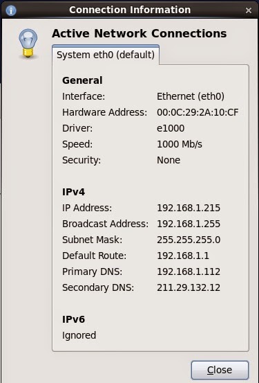
So initially Centos is installed and the machine boots with whatever default address got allocated to it. Right click the connection icon at the top left of the screen and choose Connection Information. You will get this screen:

Select and copy the hardware address. Logon to the windows 2003 machine where the DHCP server is running and run the DHCP configuration tool for Administrative Tools.

Open the scope, right click reservations and add a reservation like this (sorry I blotted out the domain name).


Paste in the hardware address and delete the colons (:).

The description doesn't matter. Leave the DNS settings as default.

Now go back to centos, right click the connection icon, choose Edit Connections, select the  System Eth0 connection and click edit.

For some reason when  I first installed the system, the network interface was configured NOT to start at boot time. This is pretty annoying as you have to connect to the console to get the machine running. Set it to connect automatically

Initially I thought I had to set the DHCP client ID. After many reboots I figured out if I set this it wouldn't work! If I just set it to blank the DHCP server gives the machine the right address and we are all good. Apply the changes, enter your root password and let it save.

In the Windows DHCP config tool, find the current reservation for the machine, right click and select delete. If you really want to be sure restart the DHCP server (right click the node below DHCP, choose All Tasks and restart). Then in Centos click the network icon, click System eth0, wait for the spinning to stop and then check the connection settings again. It now should have the configured IP.

Then I found that for whatever reason the DNS still doesn't automatically get this new entry even though the DHCP server is supposed to update it.

On Windows 2003 server, open the DNS management tool from Administrative tools, open the forward lookup zone and open your zone. Right click and choose New Host (A). Enter the name of the host (just the short part so centosdev in my case). Enter the IP address. I left the 'Create associated pointer (PTR) record checked but I got an error when I hit add host saying it couldn't. It still works so I'm not worried. This is probably because I am running on a non-routable address range.

My client computer (i.e. the computer I am accessing the centos server with) is a Windows 7 machine. I did a ipconfig /renew and then I was able to ping the new computer by name and I was able to access it via VNC.

Wednesday, 29 April 2015

Lab Power Supply - Pre-regulator

So I did some more work on the design of the pre-regulator circuit to try and increase the maximum voltage on the bulk capacitor. I also breadboarded part of the line synchronous ramp circuit which lead to a curios surprise.

The Problem with Voltage Doublers

So I got the comparators in the mail from RS and decided I would build the circuit that detects when the AC voltage goes to near zero. I haven't added the output diode, resistor and capacitor but just looked at the comparator output on the scope.


The circuit basically works except that I found there was a problem with the AC signals. Here is how it looked on the scope.


The blue and red traces are the AC1 and AC2 lines coming in. The yellow trace is the output of the comparator. As you can see it is going low when both AC signals are within one diode drop of zero (as it should) however what happened to the AC signals? They shouldn't be overlapping!
I checked the phasing of the transformer windings, and scratched my head for a while.

Eventually I decided it must have something to do with the voltage double. I removed the voltage doubler circuit and temporarily connected the gate bias regulator to the output of the capacitor (so the MOSFET gate and op amps are running at 36V generated off the main capacitor). Now the traces look as I expect!


(The green trace is the output voltage AC coupled).

I experimented with a couple more voltage doubler circuits and I emailed Peter Oakes who was extremely helpful. He had a very good idea which is instead of trying to generate the gate bias using a voltage doubler I could add another winding to the transformer. The transformers are toroidal so this is a relatively straight forward process.

I haven't tried this but will report back when I do!

Pre-regulator design

The problem with the pre-regulator is that I can't seem to get the voltage above around 33V (or the bottom of the ripple at 3A much above 30). This might be Ok but when I switch to the 15V configuration at 5A I would be lucky to get 10V out of the system.

My thought was that it was to do with the SCR drop or the SCR turning on late. I thought if I could replace it with a MOSFET transistor that is fully saturated it would work better.

I tried using the SCR to generate the voltage for the MOSFET and while I got this to work (in simulation) it had the same problem. I figured the SCR was still the limiter.

If I just drive the MOSFET from the comparator then what happens is the MOSFET will switch on and off as the voltage rises above and falls below the ramp. This will generate considerable noise and dissipate lots of power so this is no good. What I need is something that turns the MOSFET on when the firing point is reached and doesn't turn it off again until the AC reaches its zero point.

I was even considering implementing this with digital logic but thought it should be possible to do using transistors. I thought if I configure an NPN and a PNP to latch-up like an SCR does I can trigger this latch from the comparator. Then I can reset the latch using the output of the line-sync comparator which pulls low when the AC goes to zero.

The circuit I came up with was this:


So when the Fire signal goes high, it turns on Q2 which starts drawing current through Q3's base. This causes a current to flow through R2 so even when the Fire signal goes low it keeps conducting and stays latched. I had to add a diode between the Fire signal and Q2's base as otherwise it would turn the latch off. The current flowing through Q2 means the voltage at Q2's emitter goes up and it is the emitter that will drive the MOSFET gate.

Then to turn the latch off the Zero signal pulls Q1's base low which turns off Q3 and which in turn turns off Q2 and pulls the emitter low. Pretty cool huh?

I set the Fire signal to go high at the 90ms mark and then go low again at 100ms. I set the Zero signal to start high and go low at 150ms and then go high again.

Here are the traces of Zero and Fire signals:


Here they are again with the output signal superimposed:

As you can see the output starts high (don't think this matters), goes low when the zero signal goes low and then goes high again when the fire signal goes high. It stays hight until the Zero signal goes low again. This is pretty much what I wanted.

So I integrated this into the pre-regulator circuit (sorry its a bit ugly)


And actually it doesn't work that well! First of all, when the MOSFET turns on it charges the capacitor quite fast which means the output is quite peaky. I'm not sure why the op amp isn't adjusting the firing angle later but I think it just charges too fast.


In the trace above the capacitor voltage is green, the AC inputs are blue and red, the light blue ( V(n012) is the firing signal from U1. You can see it fires late the first couple of times and then earlier which over-charges the capacitor so then it doesn't fire again until much later and so on. Very chaotic.

The second thing is that when I set the desired output to max, the capacitor voltage is still too low!


Ok so at this point I'm a bit stumped. I tried increasing the gate bias voltage but this doesn't change much. I tried going back to the SCR design and replacing two of the diodes in the bridge rectifier with SCRs. This did help a bit but not much.

I had a thought however and that is the pre-regulator is only really useful at voltages below the maximum. At the maximum voltage we don't need it. I think what I will do is add a relay that basically shorts out the pre-regulator if you set the supply voltage to anything above about 28V in 30V mode or above 10 in 15V mode. This will still limit the dissipation on the MOSFET sufficiently and gives me the range I need.

I think I will stick with the SCR design. I'll build it up on a breadboard and see how it goes.

Tuesday, 28 April 2015

Lab Power Supply - Pre-regulator

The next part of the lab power supply that I wanted to tackle is the pre-regulator circuit. The problem with making a power supply without a pre-regulator is that the main pass transistor may have dissipate a lot of energy as heat in order for the circuit to operate.

You may recall my design has two modes - 0-15V and 16-30V. In 16-30V the worst case is if you set the output to 16V @ 3A in which case the MOSFET must dissipate (44-16) * 3 = 84W. Or in 15V mode you set the output to say 1V @ 5A in which case it is (22 - 1) * 5 = 105W.

These are pretty insane numbers - even a huge 0.35 degrees per Watt fan cooled heatsink will get 30 degrees above the ambient temperature.

If we instead use a pre-regulator with a switching element that dissipates little heat when it is on and nothing when it is off then we can control the voltage on the bulk capacitor and reduce the energy waste.

One approach to this problem is to use a switching pre-regulator which is essentially a switch mode power supply placed between the rectifier and the bulk capacitor. This will chop up the voltage using a MOSFET and maintain the capacitor voltage through PWM.

The problem with using a switching pre-regulator is that they create a lot of switching noise at frequencies that are hard to filter out of the final power supply output.

Linear Technology AN32

AN-32 describes an interesting circuit that uses SCRs to implement a pre-regulator. An SCR is essentially a diode with an extra leg. The SCR won't conduct unless a current is applied to the gate but once it is conducting, it doesn't matter what happens to the gate and it will keep conducting until the current flowing through the diode stops.

The way these are used is to switch the current to the bulk capacitor and thus reduce the voltage on the capacitor. The SCR is basically a diode when it is on and so dissipates little heat. When it is off it dissipates no power at all.

The voltage coming out of the bridge rectified is basically a sine wave where the negative half has been flipped up. This creates a big ripple with a cycle at double the mains frequency (100Hz where I live). The trick is to delay passing the current to the capacitor until later in the cycle. This reduces the voltage in the capacitor and the later you wait the lower the voltage.

An SCR is ideal for this as you fire the gate at the time point where you want to pass voltage to the capacitor. Then when the voltage dips back down to zero again, the SCR resets ready for the next cycle. Here is a photo from the Agilent PSU Design Handbook that illustrates the effect of varying the firing time.


The way the circuit in AN32 does this is by first generating a sawtooth voltage that is synchronised with the line frequency (a line synchronous ramp). This is generated using a comparator to detect when the voltage on the bridge rectifier is near zero and then charging a capacitor/resistor network. If you then use a comparator to compare the ramp voltage with another set voltage then the output of the comparator will turn on when the ramp goes higher than the set voltage.

Here is the line synchronous ramp I designed using a LT1716 comparator. This comparator is handy as it is safe up to 44V which is the voltage level of the transformer in series connected mode.

The inverting input is set to one diode drop above ground by the resistor and diode network. The AC input is diode-ored and then clamped to one diode drop above ground by the diode/resistor network on the right. When the output of the comparator pulls low (i.e. when both the AC signals are less than 0.6V) it pulls the capacitor low and then the capacitor slow charges back up until the cycle repeats again.

The next step is you have an op amp that compares the bulk capacitor voltage with the target voltage and this generates a voltage for a second comparator. It is this second comparator that fires at to turn on the SCR. Again I used a LT1639 for the op amp as it can handle 40V and I used another LT1716 for the other comparator.


The op amp has a capacitor/resistor network to slow down its operation enough that it acts like a servo and controls the firing point to keep the output voltage around the target. The size of the capacitor is a bit tricky since I found that if I make it too small then the circuit doesn't maintain the voltage as well (it gets low). If I make it too big then the circuit doesn't react very quickly to changes to the desired output.

This is what the voltage on the bulk capacitor (the pre-regulator output) looks like when the pre-regulator is set to generate 10V and the output is drawing about 3A. At turn on the op amp hasn't reacted yet so the capacitor gets over charged. This then bleeds off and the circuit falls into a regular firing pattern. Note the output does fall below the target 10V so I probably need to set the regulator to a few volts above the target.


Here is a close up of the AC signals, the output of the comparator driving the SCR and the output voltage. The output was set of 25V in this trace. You can see the firing point half way through the cycle.


In this trace I set the target voltage to 40V (which it can't achieve). This is as much as it can generate and unfortunately it is quite a bit below the voltage the transformer is capable of. The output of the SCR comparator is constantly at the maximum here but it still doesn't achieve even close to what I would have expected the full voltage to be.


I'm not sure why this is as in this state the SCR gate is fully on the whole time.

I also experimented with using a MOSFET to switch the voltage and an SCR just to generate the MOSFET gate signal but I couldn't get it to increase the voltage at all. This still needs some more work.

Until next time...